DECAN_F2_Service(Eng_Ver1).pdf - 第384页
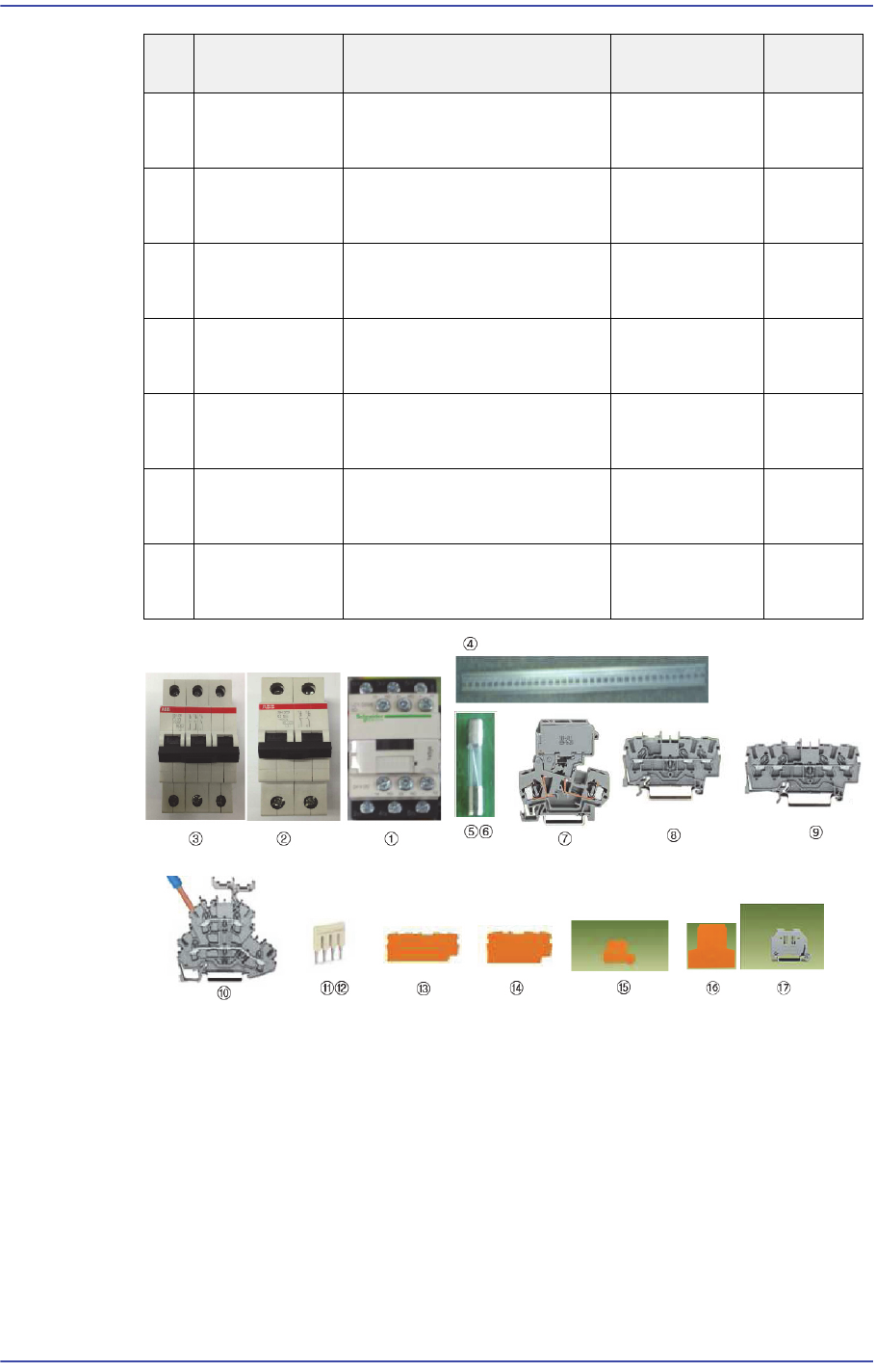
15-10 Fast & Flexible Chip Shooter DECAN F2 Service Manual 1 1 EP21-000097 TERMINAL BLOCK- JUMPER BAR 2002-405 2 12 EP21-000098 TERMINAL BLOCK- JUMPER BAR 2002-402 5 13 EP21-000099 TERMINAL BLOCK-END PLA TE 2002-1492…
15-9
Electric Device
15.4. Terminal Block Ass’y
15.4.1. Required Tools
Crosshead (Phillips) screwdriver and flathead screwdriver
T Wrench or Hex Wrench
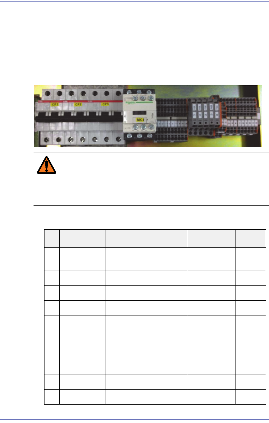
15.4.2. Terminal Block Assembly Configuration
Warning If the main circuit breaker located at the lower left on the
rear side of the machine is not turned off before performing
service, serious injury may occur. Perform servicing with the
power supply to the motor cut off without fail.
1) Part list of Terminal Block Assy
No Part No. Part Name Unit
Quantity
1 J3501040A MAGNETIC CONTACTOR LC1D096BD,
DC24V, 1A1B
1
2 EP07-000576 BREAKER,CIRCUIT SH202-C16 2
3 EP07-000731 BREAKER,CIRCUIT SH203-C16 1
4 J7051105B DIN RAIL J7051105B 1
5 J3601018A FUSE 250V 5A 3
6 J3601019A FUSE 250V 10A 2
7 EP21-000093 BLOCK,TERMINAL 281-611 5
8 EP21-000094 BLOCK,TERMINAL 2002-1301 10
9 EP21-000095 BLOCK,TERMINAL 2002-1401 10
10 EP21-000096 BLOCK,TERMINAL 2002-2201 2
15-10
Fast & Flexible Chip Shooter DECAN F2 Service Manual
11 EP21-000097 TERMINAL BLOCK-
JUMPER BAR
2002-405 2
12 EP21-000098 TERMINAL BLOCK-
JUMPER BAR
2002-402 5
13 EP21-000099 TERMINAL BLOCK-END
PLATE
2002-1492 1
14 EP21-000100 TERMINAL BLOCK-END
PLATE
2002-1392 2
15 EP21-000101 TERMINAL BLOCK-END
PLATE
2002-2292 1
16 EP21-000102 TERMINAL BLOCK-END
PLATE
281-309 1
17 EP21-000103 TERMINAL BLOCK-END
STOP
249-116 2
No Part No. Part Name Unit
Quantity
15-11
Electric Device
15.5. Front Power Panel
15.5.1. Required Tools
Crosshead (Phillips) screwdriver and flathead screwdriver
T Wrench or Hex Wrench
15.5.2. Part list of Front Power Panel
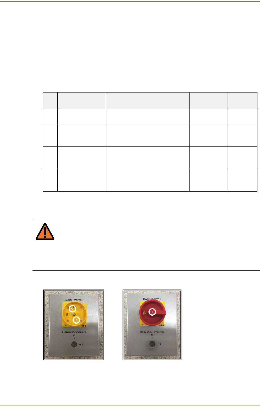
15.5.3. Front Power Panel Full assembly method
Warning If the main circuit breaker located at the lower left on the
rear side of the machine is not turned off before performing
service, serious injury may occur. Perform servicing with the
power supply to the motor cut off without fail.
1) Assemble the main switch to the panel.
2) Insert the Safeguard Override Key to the panel.
No Part No. Part Name Unit
Quantity
1 J3406005A LOAD SWITCH PI-25 1
2 FC09-003401A BRACKET-FRONT ELEC
PANEL
1
3 AM03-01079A SAFEGUARD_OV_SW_KE
Y_CABLE_ASSY
SM411-
SC008
1
4 AM03-010917A CABLE ASSY-
MAIN_SWITCH_TRANS
SM511_PW
005
1