DECAN_F2_Service(Eng_Ver1).pdf - 第414页
17-2 Fast & Flexible Chip Shooter DECAN F2 Service Manual 17.2. Necessary Data according to Problems When the following problems occur , transmit the corresponding file. 8 All Files in D:\ErrV isFile Folder In case o…
17-1
Troubleshooting
Chapter17. Troubleshooting
17.1. Data Needed to be Collected When a Problem Occurs during Machine
Operation
Ref When a problem occurs, if there is C:\SmartCM(C:\SmartCM)
directory BIN, all directories excluding Vmeipl and RT Telemetry in
the case of problems with the machine, and a vision error image in the
case of vision error, it is easy to perform analysis
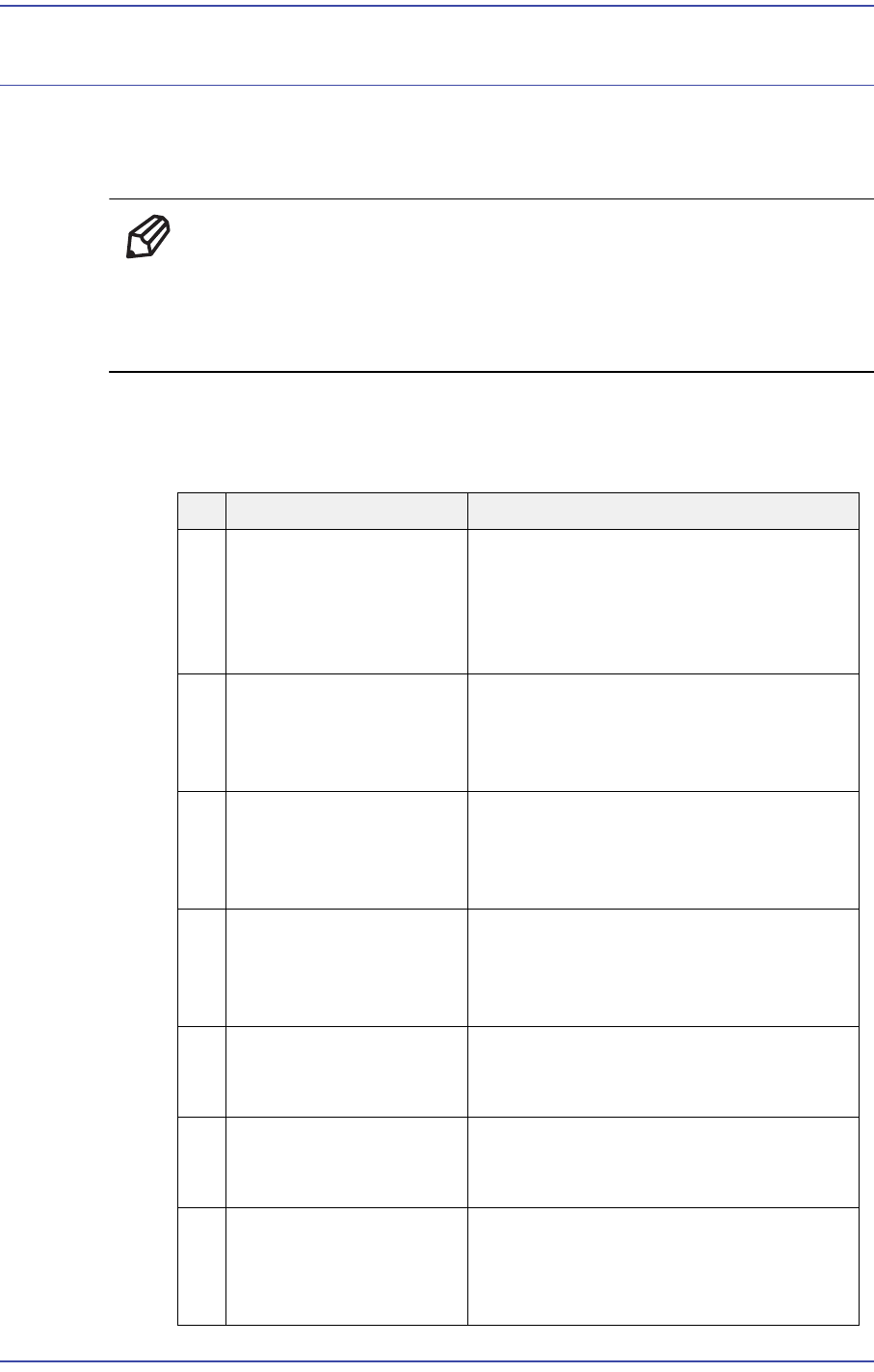
When a problem occurs with the machine, send the following data in a compressed file
format, such as *.ZIP, etc., immediately or as soon as possible.
NO Necessary File Data Description
1 PCB File in Use It is possible to reproduce the movement
with the PCB file to which a problem
occurs and examine whether the PCB
file itself has a problem or it has a
problem when changing data with OLP.
2 All Files in
C:\SmartCM\Log
(C:\SmartCM\Log)
Folder
It is possible to see the operational
activities performed by the operator and
to track the state of the MMI, RT and
Vision by time.
3 All Files in
C:\SmartCM\System
(C:\SmartCM\System)
Folder
It is possible for the user to try to
reproduce the performed operation
under the executed program
environment.
4 All Files in
C:\SmartCM\Temp
Folder
When an error related to the optimizer
occurs, it is possible to trace the PCB
before and after the optimizer and track
the cause of the error.
5 All Files in
C:\SmartCM\PdInfo
Folder
In case of a problem related to the dump
rate, this file is necessary additionally.
6 All Files in
C:\SmartCM\PartDB
Folder
When a problem occurs during part
registration in the Part DB, it is possible
to see it by reproducing it.
7 All Files in D:\SMBackup
Folder
From the system backup status before
and after work, it is possible to check
when a problem occurred or whether
abnormal operation occurred.
17-2
Fast & Flexible Chip Shooter DECAN F2 Service Manual
17.2. Necessary Data according to Problems
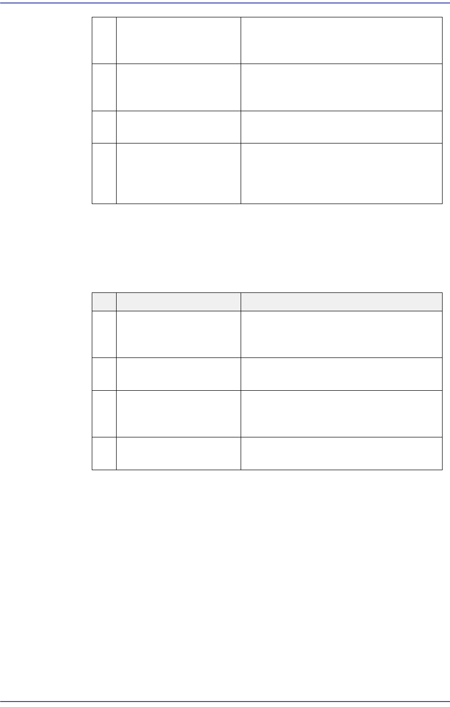
When the following problems occur, transmit the corresponding file.
8 All Files in D:\ErrVisFile
Folder
In case of a problem related to the vision
recognition, this file is necessary
additionally.
9 RT Telemetry File When the machine operates abnormally
during production and operation, this file
is necessary to analyze the problem.
10 Vision Error Image File Used to check any problem with the
recognition result.
11 Screen Capture File When an error message related to a
window occurs or an error occurs during
MMI screen manipulation, this file is
necessary to check the problem.
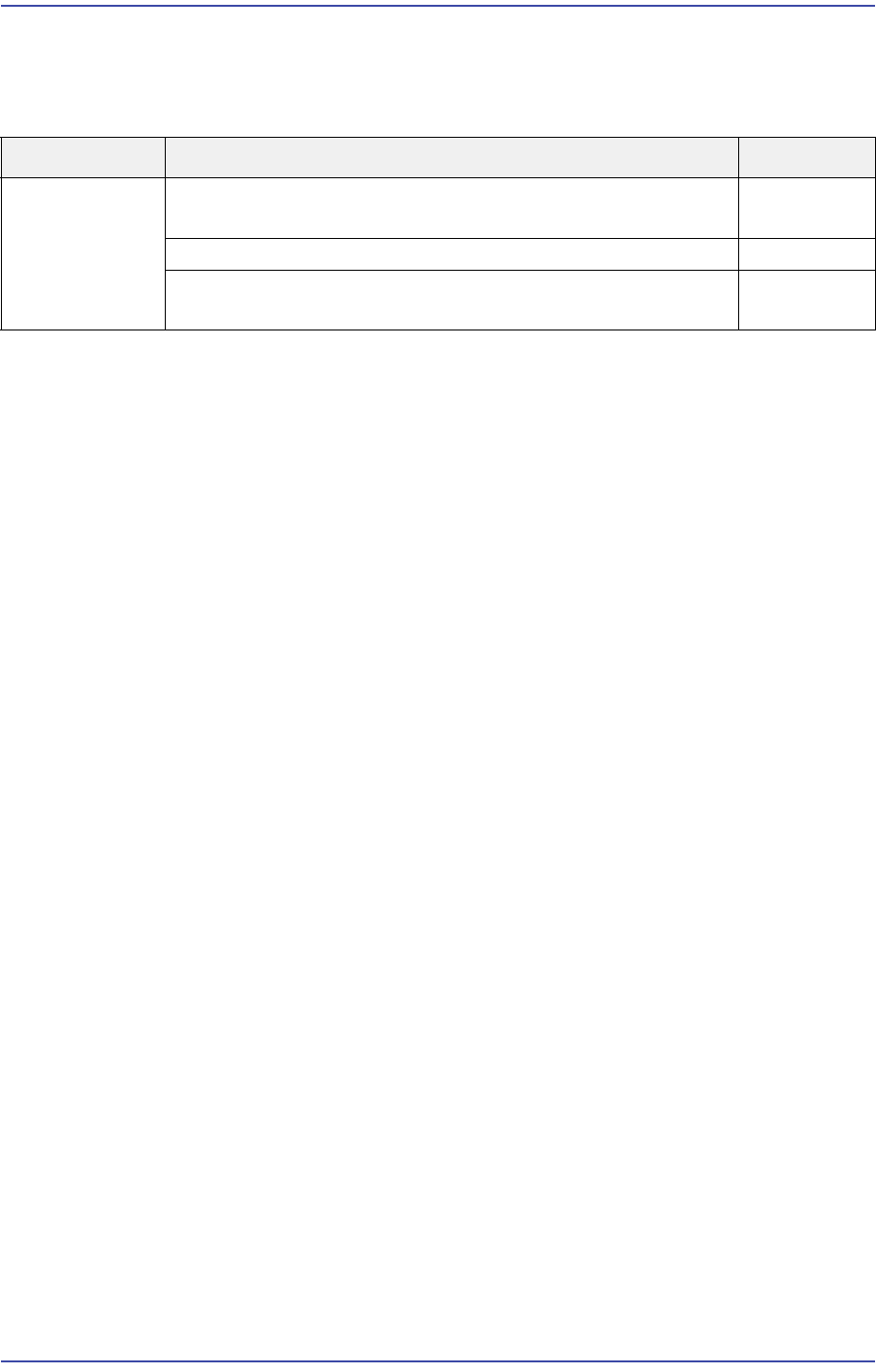
NO Necessary File Data Description
1 PCB, LOG, SYSTEM,
SMBACKUP, Screen
Capture, etc.
When an error occurred during MMI
programming or in use
2 PCB, LOG, SYSTEM,
RT Telemetry, etc.
When the machine exhibits a problem
during operation or production
3 PCB, LOG, SYSTEM,
PDInfo, Vision Error
Image, ErrVisFile, etc.
When the part dump rate increases and
a vision error occurs
4 PCB, LOG, SYSTEM,
TEMP, etc
When an error occurs before and after
the optimizer
17-3
Troubleshooting
17.3. Process Trouble Shooting
17.3.1. PC Booting Failure
E0500 turning on the power supply, a ‘No Signal’ message appears on the monitor
[Cause]
The input voltage (220V) and output voltage (5V, 12V) of the PC power supply have a
problem
The HDD was damaged due to frequent booting error and failure
The SBC board and CPU are defective (a beep sound occurs)
The board operates abnormally due to an increase in the internal temperature of the PC
rack
The back plane is defective (no beep sound)
Defective vision board and MMI board (Defective RS232 port)
Complex defects : Defective SBC board and back plane board, defective CPU, virus
infection, CUP temperature increase, etc.
Unstable main power supply
The CPU is overheated due to a defective CPU cooling fan
The monitor is defective or the signal cable is not connected
[How to Check]
Check whether the cooling fan on the Control rack operates properly when turning on
the power. If the fan does not operate, check whether the input voltage (220V) and
output voltage (5V, 12V) of the PC power supply are normal Check the input end
voltage (+12V) of the external power supply of the vision board.
Check whether the HDD is properly recognized in the CMOS Setup
Check whether the priority of the HDD is 1 in the MMI SBC CMOS boot sequence.
Perform the CMOS reset test and check whether the message ‘CMOS was set with the
default value’ is displayed on the screen
Check whether the temperature at the site is higher than 24ºC
Cause Description Remarks
Defective part Turning on the power supply will display ‘No Signal’ on the
monitor.
E0500
Blue screen occurs while booting or running the PC. E0501
The PC stops when it almost starts Windows while booting
the PC
E0502