DECAN_F2_Service(Eng_Ver1).pdf - 第449页
17-37 Troubleshooting [Measures] Eliminate the cause of the interference that occurred while transferring the PCB from the current machine to the next ma chine. Check the conveyor belt condition. Replace the step m…

17-36
Fast & Flexible Chip Shooter DECAN F2 Service Manual
Replace the idler.
E0909 When transferring PCBs from the previous machine to the entry station, a PCB is
jammed
[Cause]
Interference occurs while transferring the PCB from the previous machine to the
current machine
Defective conveyor belt
Defective step motor
Defective idler
[How to Check]
Check whether interference occurs while transferring the PCB from the previous
machine to the current machine
Check whether the conveyor belt moves properly
Replace the step motor and check whether the same problem occurs
Check whether the idler works properly
[Measures]
Eliminate the cause of the interference that occurred while transferring the PCB from
the previous machine.
Check the conveyor belt condition.
Replace the step motor.
Replace the idler.
E090A Interference occurs while transferring the PCB from the current machine to the next
machine
[Cause]
Interference occurs while transferring the PCB from the current machine to the next
machine
Defective conveyor belt
Defective step motor
Defective idler
[How to Check]
Check whether interference occurs while transferring the PCB from the current
machine to the next machine
Check whether the conveyor belt moves properly
Replace the step motor and check whether the same problem occurs
Check whether the idler works properly
17-37
Troubleshooting
[Measures]
Eliminate the cause of the interference that occurred while transferring the PCB from
the current machine to the next machine.
Check the conveyor belt condition.
Replace the step motor.
Check the idler.
E090B After the BUT moved down, the PCB does not move to the exit station
[Cause]
The PCB is jammed
The PCB is damaged
[How to Check]
Check the cause of the PCB jamming
Check whether the PCB is damaged
[Measures]
Remove the cause of the PCB jamming.
Replace the PCB with another one.
17.3.6. Head(E0A)
E0A00 The Ball Spline is damaged
[Cause]
The Ball Spline collided with something
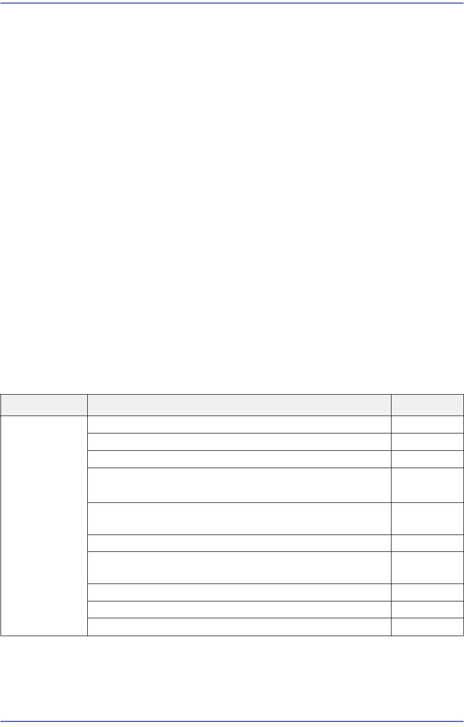
Cause Description Remarks
Head The Ball Spline is damaged E0A00
(EMER) An alarm was detected on the Axis H# E0A01
An error (follow-up error) occurred to the $A axis E0A02
Axis $A homing error
- AMP, index mark, auxiliary home sensor…
E0A03
A pneumatic system error occurred before (while) Warning
Head 1 picked up a part
E0A04
Axis $A Error: Failed to find the Home Sensor E0A05
HEAD #3 moves too far out of the part placement point on
the PCB
E0A06
[EMER] Axis # motor or origin position has been changed E0A07
The Head $H picked the part $P at its edge in the feeder $F E0A08
Axis $A home calibration is not calibrated E0A09

17-38
Fast & Flexible Chip Shooter DECAN F2 Service Manual
The Ball Spline ball has fallen out
The Z-axis LM-guide ball has fallen out.
[How to Check]
Check what the Ball Spline has collided with.
Check the up/down and left/right movement of the Ball Spline.
Check the Z-axis LM Guide.
[Measures]
Replace the Ball Spline assembly and calibrate it.
Replace the corresponding Z-axis LM-guide and calibrate it.
E0A01 (EMER) An alarm was detected on the Axis H#
[Cause]
Encoder power cable is incorrectly connected
Since the ANC nozzle setting was incorrectly performed, an alarm occurred due to Z-
axis load
The Z-motor is defective
Defective contact of the CN8 cable in the SEDES Slave Board and SEDES CN2 cable
in the SEDES Board (Applicable only to SM series machines excluding the DECAN
F2, SLM, SM471 and SM48X machines.)
Problem with part thickness and backup pin setting
Defective servo driver
Unstable main power supply
Defective SEDES board
(Rear Z1~6 and R1, 2 and 3 alarm lamps are blinking at the Motor I/O)
(Applicable only to SM series machines excluding the DECAN F2, SLM, SM471 and
SM48X machines.)
Defective flat cable assembly
Occurrence of alarm due to noise (The Z limit is changed)
The Head Z-axis belt fixing bracket bolt has fallen out
When checking the P/S#2 connected to the M/C#1, 24V is not outputted (18.6V)
[How to Check]
1. Check the up/down and left/right movement of the Z-axis.
2. Check the grease application status.
3. Check the Z offset data.
4. Check the assembling state of the power cable and encoder cable.