DECAN_F2_Service(Eng_Ver1).pdf - 第147页
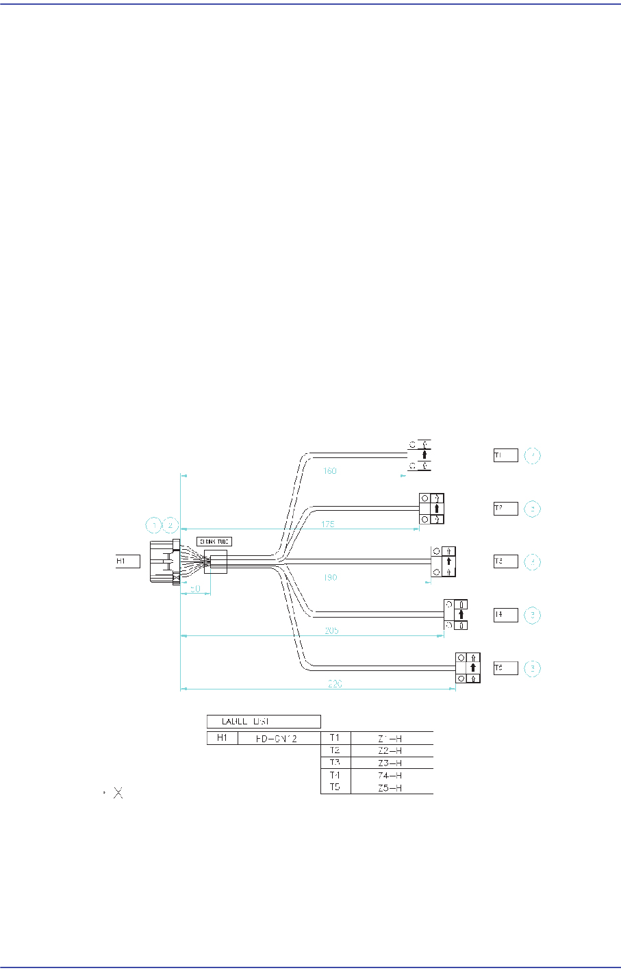
5-47 Head Pin Assignment of ZAxis Home Sensor Cable
5-46
Fast & Flexible Chip Shooter DECAN F2 Service Manual
5.9.6. How to replace the Z-axis sensor individually (Z6~Z10)
1) Remove the R-axis home sensor cable from the machine as shown in Figure 1.
After removing the CN11 connector of the Head IF board, remove the R-axis home
sensors (5 sets).
2) Remove the area treated with a shrink tube as shown in Figure 1.
3) Replace the R-axis home sensor.
R1 Home Sensor: Connect the sensor to A1/A4/B4 referring to Figure 2.
R2 Home Sensor: Connect the sensor to A2/A5/B5 correctly referring to Figure 2.
R3 Home Sensor: Connect the sensor to A3/A6/B6 correctly referring to Figure 2.
R4 Home Sensor: Connect the sensor to A2/B1/B5 correctly referring to Figure 2.
R5 Home Sensor: Connect the sensor to A3/B2/B6 correctly referring to Figure 2.
4) After replacing the Z-axis sensor, finish the area where the connector and cable is
connected and then they are treated with a shrink tube by using insulation tape so that
current does not leak out.
5) After replacing the sensor, connect the connector to the Head I/F board and connect
the Z-axis home sensors (5 sets) to the head spindle again.
Z Axis Home Sensor Cable

5-47
Head
Pin Assignment of ZAxis Home Sensor Cable