DECAN_F2_Service(Eng_Ver1).pdf - 第165页
6-15 Conveyor 4) Unscrew the fixing bolts (2-M5*10 ) securing the Motor using a wrench and remove it. 5) Unscrew the setscrew securing the motor to remove it and remove the motor pulley and set screw . 6) Replace the Mot…
6-14
Fast & Flexible Chip Shooter DECAN F2 Service Manual
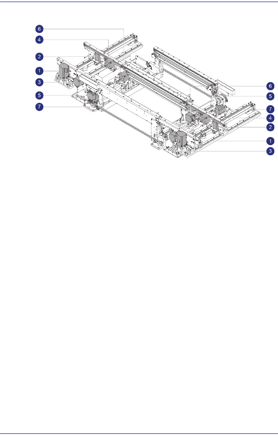
6.3. Conveyor Motor
1: Entry / Exit Zone Frame Width adjustment Motor
2: Entry / Exit Zone Rear Frame Width adjustment Motor
3: Entry / Exit Zone Front Frame PCB transfer Motor
4: Entry / Exit Zone Rear Frame PCB transfer Motor
5: Work Zone Front Fix Frame PCB transfer Motor
6: Work Zone Front Move Frame PCB transfer Motor
7: Work Zone Power transmission Motor
6.3.1. Required Tools
Tension Gage (U-505)
Flathead screwdriver
T-Wrench (other tools supplied) or Hex Wrench
6.3.2. Entry / Exit Zone Frame Width adjustment Motor Replacement Procedure
1) Manipulate to increase the conveyor width as wide as possible.
2) Close the PC as usual and turn off the main switch at the front of the machine.
3) Please remove the Cable that is connected to the Motor.
6-15
Conveyor
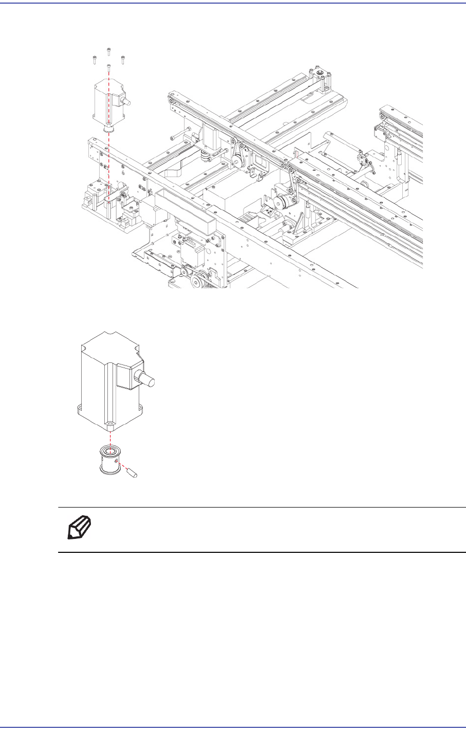
4) Unscrew the fixing bolts (2-M5*10) securing the Motor using a wrench and remove it.
5) Unscrew the setscrew securing the motor to remove it and remove the motor pulley
and set screw.
6) Replace the Motor with a new one.
Ref The part number of the new Motor is EP08-000204.
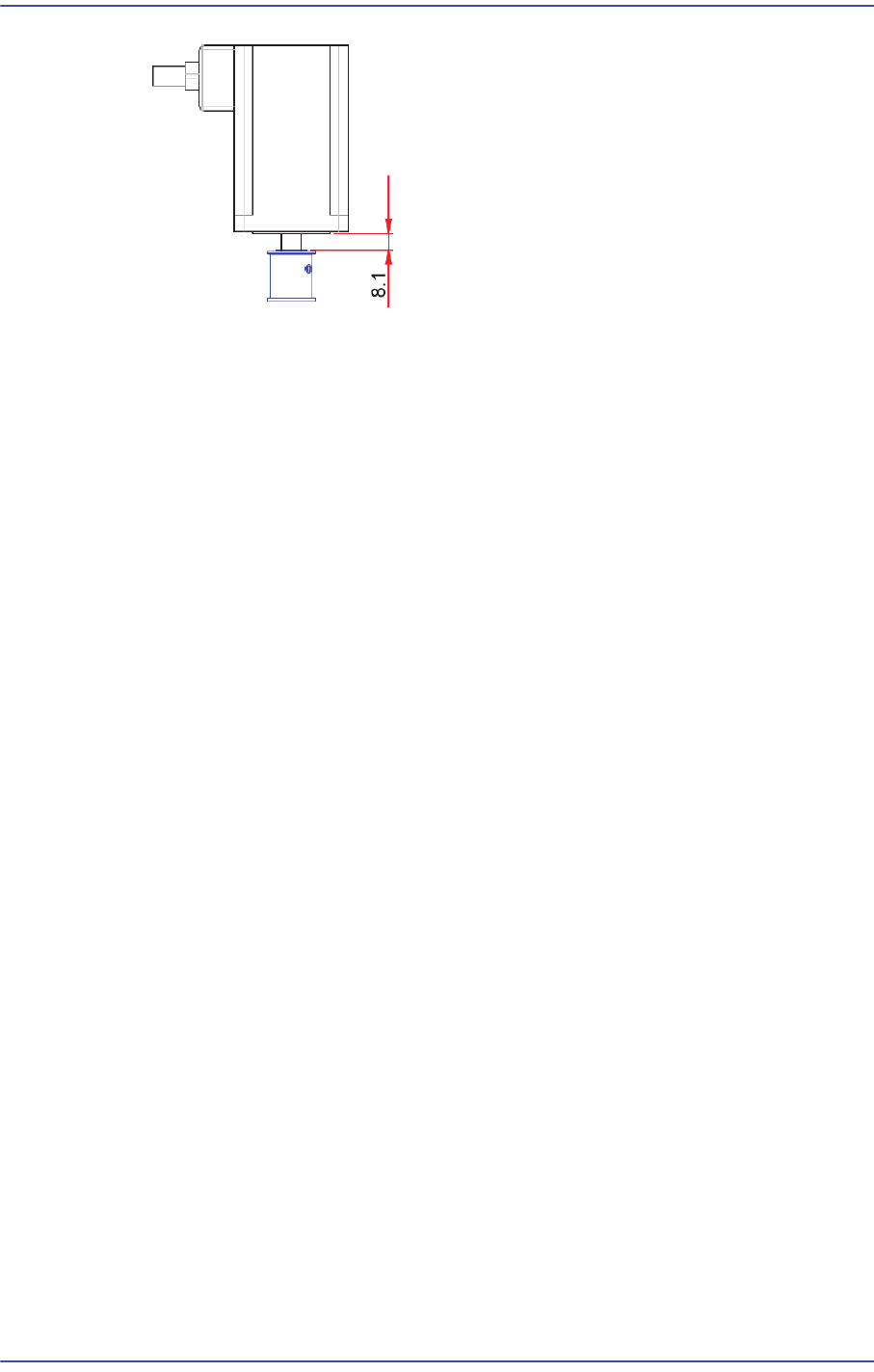
7) When assembling the motor-pulley, refer to the following.
6-16
Fast & Flexible Chip Shooter DECAN F2 Service Manual
8) After assembling the motor, adjust the belt tension referring to the Belt Replacement
Procedure.
Entry / Exit Zone Width adjustment Belt: MC05-000151
9) Execute the ‘Conveyor Utilities’ dialog box to check if the conveyor moves properly.
After selecting the corresponding station, click the <Belt Run> button and check
whether the motor is operating properly.
10) Check the following.
A)When operating each motor continuously, check whether PCBs are smoothly
transferred.
B)When operating each motor continuously, check whether any abnormal noise
occurs.
C)Check whether the feeding speed of each motor is properly set.
11) Perform the following calibrations.
Motor you replace the Calibrate Home All Axis execution
Time: 0.5 hour
6.3.3. Entry / Exit Zone Rear Frame Width Adjustment Motor Replacement
Procedure
1) Manipulate the teaching box to increase the conveyor width as wide as possible.
2) Close the PC as usual and turn off the main switch at the front of the machine.
3) Please remove the Cable that is connected to the Motor.
4) Unscrew the fixing bolts (4-M4*8) securing the Motor Bracket using a wrench and
remove it.
Unscrew the fixing bolts (4-M3*6) securing the Motor using a wrench and remove it.