DECAN_F2_Service(Eng_Ver1).pdf - 第479页
17-67 Troubleshooting 3. Check that under what si tuation, the alarm occurs. 4. Check the operation state of the Servo Driver , Coupling, Motor and Ball Screw in order . [Measures] Replace the X-axis Servo Driver . E0D…

17-66
Fast & Flexible Chip Shooter DECAN F2 Service Manual
Unstable voltage [momentary power failure]
Defective Axis Sensor Board (LED is not turned on when checking the Axis Sensor
Board)
[How to Check]
1. Check the status of the movement in the X direction in the Ready Off state. (Check
for any problems with the movement)
2. Perform a homing operation test in the Ready On state.
3. Check that under what situation, the alarm occurs.
4. Check the operation state of the Servo Driver, Coupling, Motor and Ball Screw in
order.
[Measures]
After approximately 1 hour has elapsed since the 24V power supply drop, check
whether the X-Y frame works normally.
Replace the Axis Sensor Board.
E0D0A An alarm occurs to the axis driving system sporadically
[Cause]
The FR Operate CN1 (Front or Rear Operation Panel) cable contact is defective.
Defective contact of the relay in the safety control board and DC power board
[How to Check]
1. Check the status of the movement in the X direction in the Ready Off state. (Check
for any problems with the movement)
2. Perform a homing operation test in the Ready On state.
3. Check that under what situation, the alarm occurs.
4. Check the operation state of the Servo Driver, Coupling, Motor and Ball Screw in
order.
[Measures]
Reassemble the FR Operate CN1 (Front or Rear Operation Panel) cable.
Reassemble the relay in the safety control board and DC power board.
E0D0B A follow-up error occurred to G1F-X
[Cause]
Defective X-axis Servo Driver
[How to Check]
1. Check the status of the movement in the X direction in the Ready Off state. (Check
for any problems with the movement)
2. Perform a homing operation test in the Ready On state.

17-67
Troubleshooting
3. Check that under what situation, the alarm occurs.
4. Check the operation state of the Servo Driver, Coupling, Motor and Ball Screw in
order.
[Measures]
Replace the X-axis Servo Driver.
E0D0C Homing error (Index Mark Error) occurred
[Cause]
Defective contact of the Twin AXIS Board
[How to Check]
1. Check the status of the movement in the X direction in the Ready Off state. (Check
for any problems with the movement)
2. Perform a homing operation test in the Ready On state.
3. Check that under what situation, the alarm occurs.
4. Check the operation state of the Servo Driver, Coupling, Motor and Ball Screw in
order.
[Measures]
Reassemble the Twin AXIS Board.
E0D0D Thermal Mapping Timing Error
[Cause]
A timeout error occurred while recognizing the fiducial.
[How to Check]
1. Check the state of the Mapping Fiducial Mark at the top of the conveyor.
2. Perform calibration.
3. Check the system constant data.
4. Check the Move Camera.
[Measures]
Perform calibration [Thermal, Gantry Mapping].
17-68
Fast & Flexible Chip Shooter DECAN F2 Service Manual
17.3.10. Errors related to feeder base and ANC (E0E)
E0E00 The feeder part $P clamp cleared the [Open Error] Some of the feeder slots does not
work (Index signal does not work)
[Cause]
The Feeder I/O Board U43 IC is damaged since a short-circuit occurred to the left and
right feeder boards.
The left and right feeder boards are defective.
The Feeder Input Ext. Board is defective.
The contact of the Feeder Input Ext. Board is defective.
[How to Check]
1. Test the manual operation of the slots experiencing a problem with the
corresponding feeder base and check I/O.
2. Check the Feeder Base Board slots.
3. Check the air fittings of the feeder base.
4. Check the Feeder I/O Board and Feeder Input Ext. Board.
[Measures]
Replace the Feeder I/O Board.
Replace the left and right feeder base board.
Replace the Feeder Input Ext. Board.
Reconnect the Feeder Input Ext. Board.
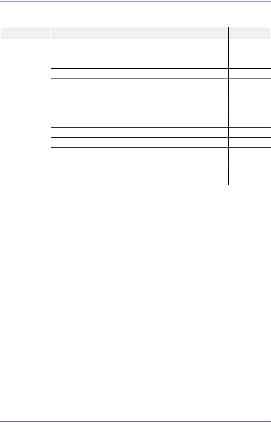
Cause Description Remarks
Errors related to
feeder base and
ANC
The feeder part $P clamp cleared the [Open Error]
Some of the feeder slots does not work (Index signal does
not work)
E0E00
The Feeder Unlock Sensor detected a part E0E01
An error occurred while changing a nozzle for the head#
(Alarm, PUT or GET error)
E0E02
Cannot open (close) the ANC shutter E0E03
Cannot mount a nozzle since there is no nozzle on the head E0E04
When the machine is turned on, feeders feed a part first E0E05
The feeder is not removed and installed smoothly E0E06
Failed to move up the front docking cart E0E07
Only one part in the vibration feeder is continuously picked
up
E0E08
The [Open Error] of the Feeder Part $P Clamp is cleared.
(Vibration feeder Index is defective.)
E0E09