DECAN_F2_Service(Eng_Ver1).pdf - 第95页
4-7 X Frame 7) Remove the ball screw by inclining it so that it is not damaged due to collision with other modules. 8) Replace the Ball Screw with a new one. Ref The part number of the new Ball Screw is MC13-00 0125. 9) …
4-6
Fast & Flexible Chip Shooter DECAN F2 Service Manual
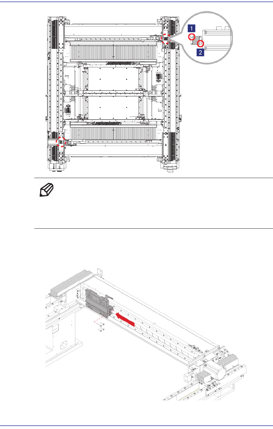
Ref When replacing only the X-axis motor, remove only the set
screw(No2) near the motor and when replacing only the ball screw,
remove only the set screw(No1) near the ball screw.
6) After moving the Head Base as far as possible to the left, unscrew the ball screw as
well as the Head Base fixing bolts (4-M5*20) to remove the head base.
4-7
X Frame
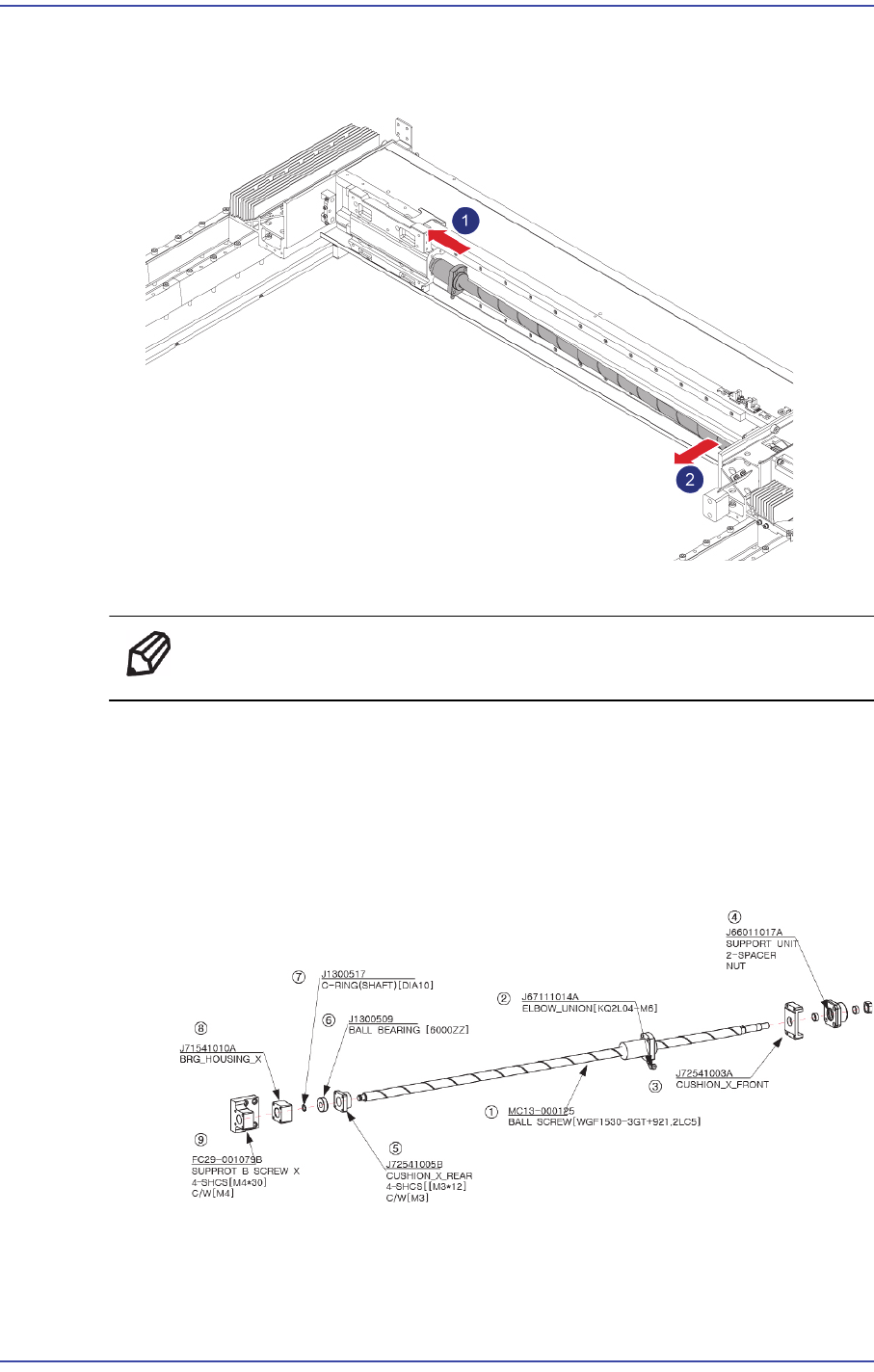
7) Remove the ball screw by inclining it so that it is not damaged due to collision with
other modules.
8) Replace the Ball Screw with a new one.
Ref The part number of the new Ball Screw is MC13-000125.
9) When assembling, refer to the following.
Tighten Support B Screw X by applying 40kgf-cm torque.
When assembling the Cushion X Rear, apply Loctite and assemble it up to the
position at which the screw comes in contact with the cushion.
After assembling C ring, check whether it can be turned by hand.
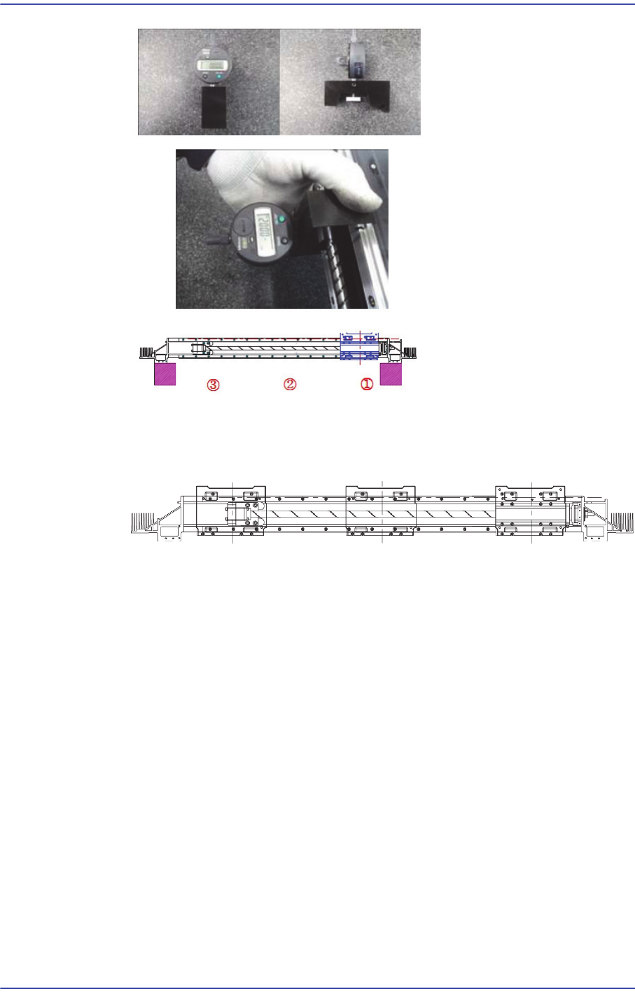
After assembling the Ball Screw, measure the side height at the position shown in the
following figure using a jig.
4-8
Fast & Flexible Chip Shooter DECAN F2 Service Manual
Please measure the concentricity of Ball Screw after assembly.
When assembling the Base Head Carrier, please assemble it using Jig at three points
left, right, in the middle as shown in the following figure.
10) Turn on the main switch on the front side of the machine and boot the PC once the
assembling is completed.
11) Perform the following calibrations.
Axis Home Calibration
Common X-Y (1'st)
Thermal Mapping
Gantry Mapping
ANC, Position Teaching
Total Time : 0.8Hour