DECAN_F2_Service(Eng_Ver1).pdf - 第565页
18-45 Machine Calibration 18.3.10. Head & Camera Calibration Perform the camera calibration function. The calibration sequen ce and tools necessary for calibration are as follows. Fiducial Camera Offset Calibration…
18-44
Fast & Flexible Chip Shooter DECAN F2 Service Manual
18.3.9. ANC Pos. Scan
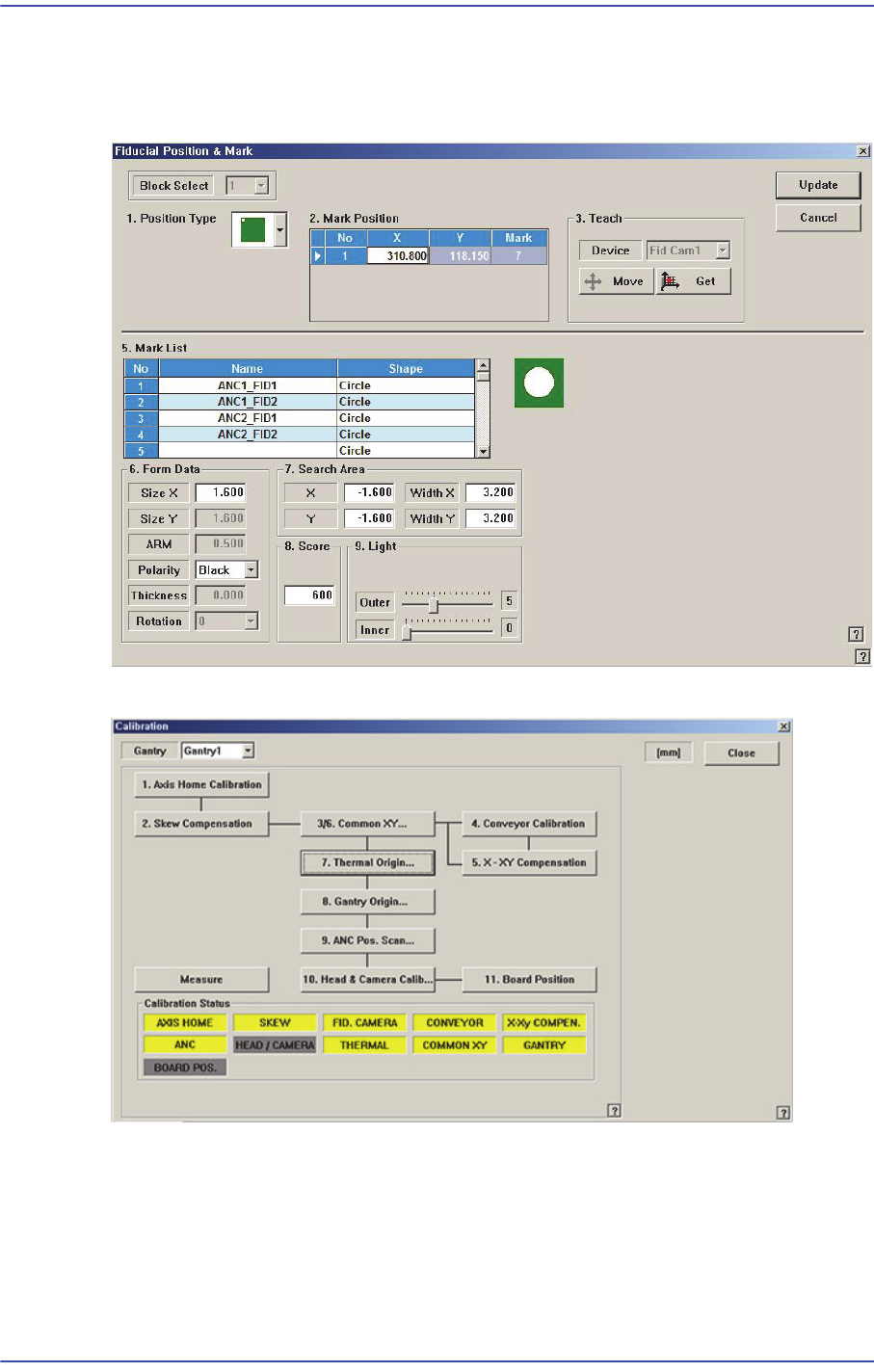
Teach the 2 fiducial marks on the top surface of the ANC. Compensate the relative
coordinate system of the front and rear ANCs.
Refer to “6.3 Fiducial Mark Setup”for more information.
18-45
Machine Calibration
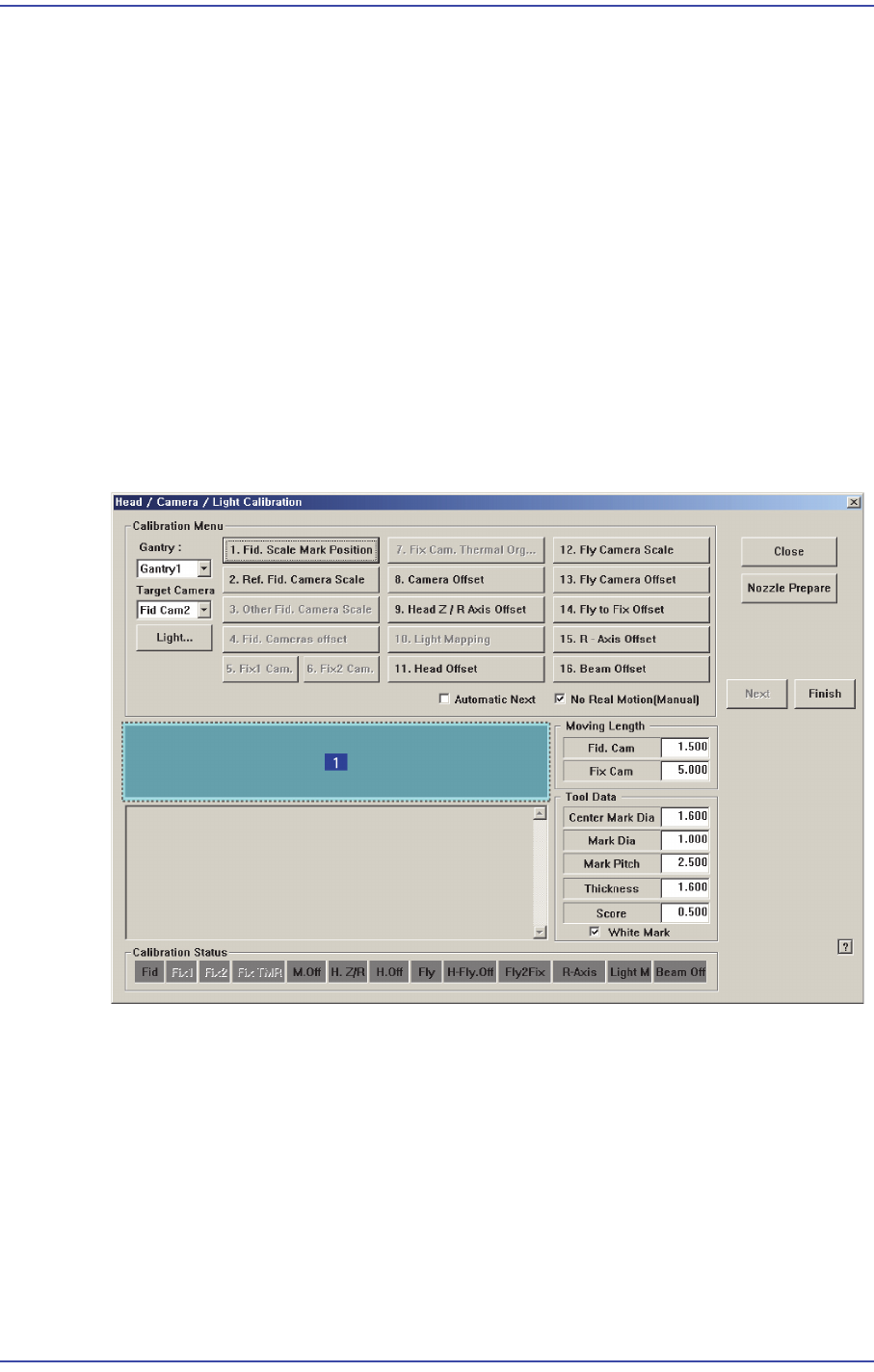
18.3.10. Head & Camera Calibration
Perform the camera calibration function. The calibration sequence and tools necessary for
calibration are as follows.
Fiducial Camera Offset Calibration (Calibration Tool)
Head Z & R Offset Calibration (CN040 Nozzle)
Light Mapping (Light Fly Nozzle)
Head Offset Calibration
Fly Camera Scale & Rotation Calibration
Fly Camera Offset Calibration
Fly To Fix Offset Calibration
R-Axis Offset Calibration
Figure18.15 “Head/ Camera/ Light Calibration” dialog box
1: Head/ Camera/ Light Calibration” dialog box
<Calibration Menu> group
Select an item to be calibrated. If you click the button of a specific item, the
description on the works to be performed are displayed in the message box in order.
Follow the instructions to complete the calibration.
<Gantry> combo box
Select the Gantry for performing Calibration
<Target Camera> combo box
18-46
Fast & Flexible Chip Shooter DECAN F2 Service Manual
Select the camera to set light value.
<Light…> button
Set the light value for the selected camera.
18.3.10.1. Fiducial Camera Offset Calibration
Measure the offset between the center of the fiducial camera and the first head (Head 1,
Head7) of each gantry.
This offset measurement must be completed to be able to use the Auto Nozzle Change
function for calibrations that follow. This process is performed only in the Manual Mode.
In order to perform calibration of Fly-Camera Scale Calibration, first check if the
calibration tool is placed on the calibration tool position of the front ANC.
The following is the procedure to calibrate the Fid Cam Offset of the head;
1. If the <8. Camera Offset> button is clicked, the message “First, We must Put all
Nozzles From Heads on Manually.
To Move Down Z Axis, Click [Next]” appears in the message box. Click the <Next>
button to move down the Z axis of the head in order to remove all nozzles inserted in
the nozzle-holder manually.
2. Then, after the head assembly moves to the designated position, move all Z-axes
down. At this time, remove all inserted nozzles manually.
3. Then the message “Next Attach the Calibration Tool to Head 1. Click [Next] for
Moving Down Head. After Moving, Attach the Tool to head Manually” appears. Click
the <Next> button after inserting the calibration tool in the nozzle-holder of Head #1
manually.
4. The message “Move To Center Position Of Calibration Tool. To Move, Click[Next]”
appears in the message window.
Click the <Next> button to move the fiducial camera to the calibration tool position on
the top surface of the ANC. At this time, adjust the position of the calibration tool so
that the fiducial mark at the calibration tool is on the center of the cross hair of the
SMVision window.