DECAN_F2_Service(Eng_Ver1).pdf - 第225页
10-11 Y-Axis Frame 10.3. Sensor 10.3.1. Required Tools T Wrench (other tools supplied) or Hex W rench T orque Wrench 10.3.2. Location of Sensor 10.3.3. Sensor Repl acement Procedure 1) Close the PC as usual and turn …
10-10
Fast & Flexible Chip Shooter DECAN F2 Service Manual
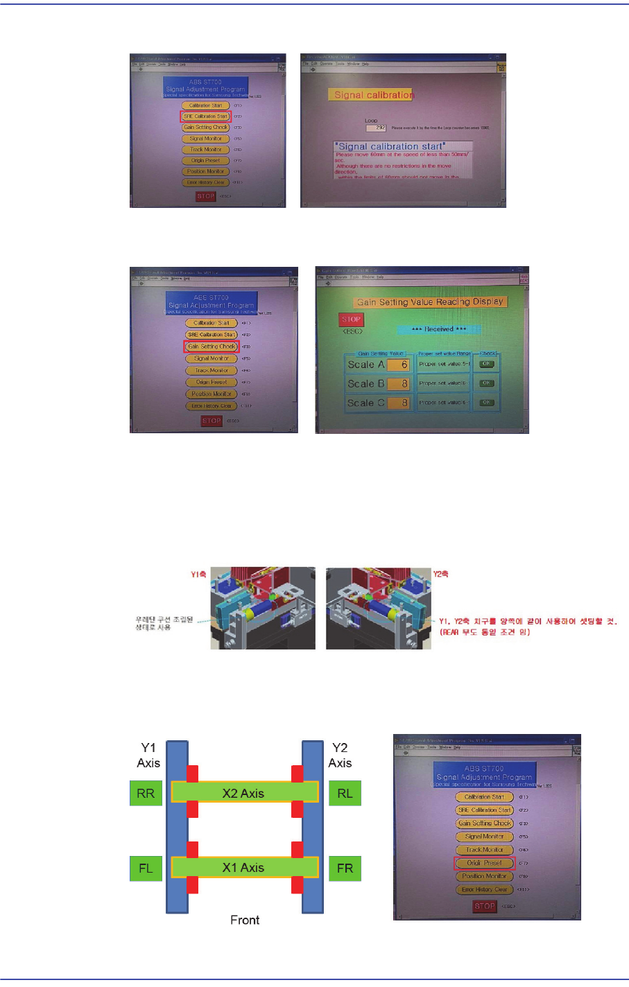
(The Y-axis moves to the front once and then to the rear once again.)
Click the ‘Gain Setting Check’ button to perform setup so that the scale values of
the A, B and C phases fall within the specified range.
Click the ‘Origin Preset’ button to check again whether the read values of A, B
and C phases as well as MED-FINE and COAMED values fall within the
specified range.
To calibrate the Y-axis, as shown in the figure, in close contact with Jig O points
(Origin) to the Setting.
After setting the origin of the X and Y axes (Jig in a state close to the axis), click
the ‘Position Monitor’ to check whether the FL RR is -55mm±1.0mm and FR RL
is +55mm ±1.0mm.
10-11
Y-Axis Frame
10.3. Sensor
10.3.1. Required Tools
T Wrench (other tools supplied) or Hex Wrench
Torque Wrench
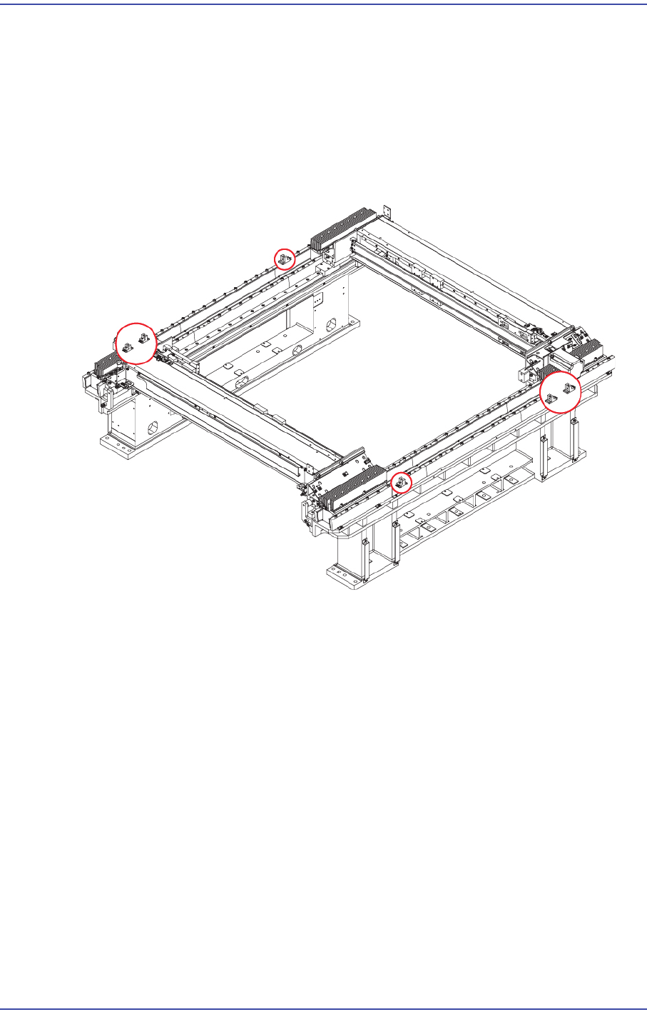
10.3.2. Location of Sensor
10.3.3. Sensor Replacement Procedure
1) Close the PC as usual and turn off the main switch at the front of the machine.
2) Remove the power of Motor and encoder cable connector.
10-12
Fast & Flexible Chip Shooter DECAN F2 Service Manual
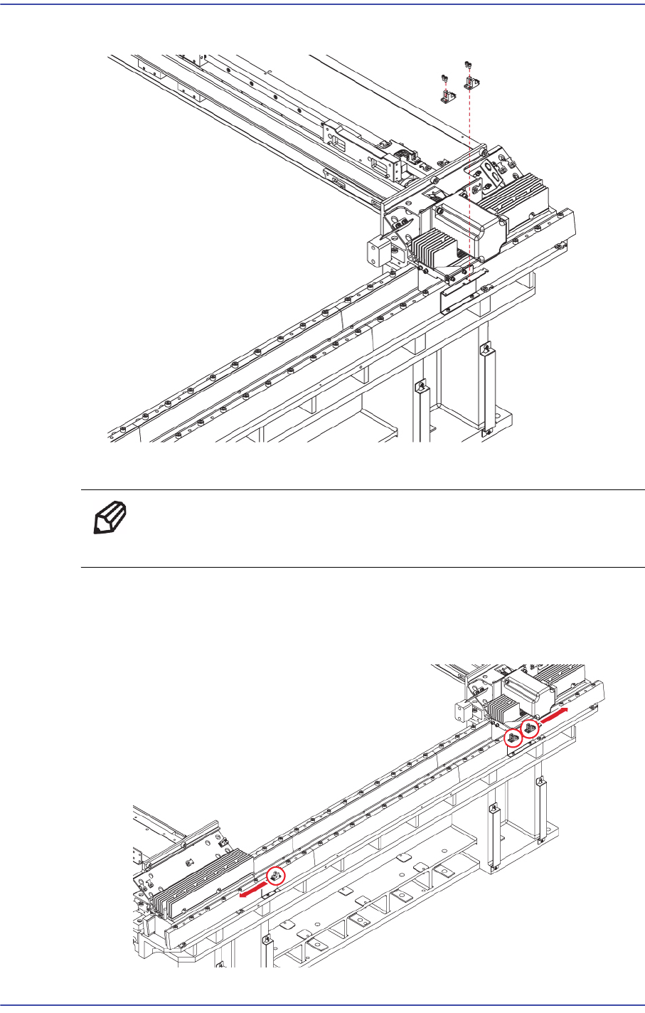
3) Unscrew the fixing bolts(2-M3*6) securing the Sensor using a wrench and remove it.
4) Assemble in the Y Fame a new Sensor.
Ref The part number of the new Sensor is J3212022A.
5) When assembling the Sensor, refer to the following.
When assembling the sensor, have the sensor connector facing in the direction as
shown in the following figure and secure it with cable ties.