DECAN_F2_Service(Eng_Ver1).pdf - 第266页
12-16 Fast & Flexible Chip Shooter DECAN F2 Service Manual 12.5. New Dual Head Amp Driver 12.5.1. Alarm Code When an error occurs, the 7 se gment LEDs of the motor drive will flicker . As well, the corresponding alar…
12-15
Motor Driver
18) Perform setups for the remaining axes from Step 1 in the same manner as above.
CautionFY1 and RY1 as well as RY2 and FY2 can be set simultaneously.
However, FY1 and FY2 as well as RY1 and RY2 must not be set
simultaneously.
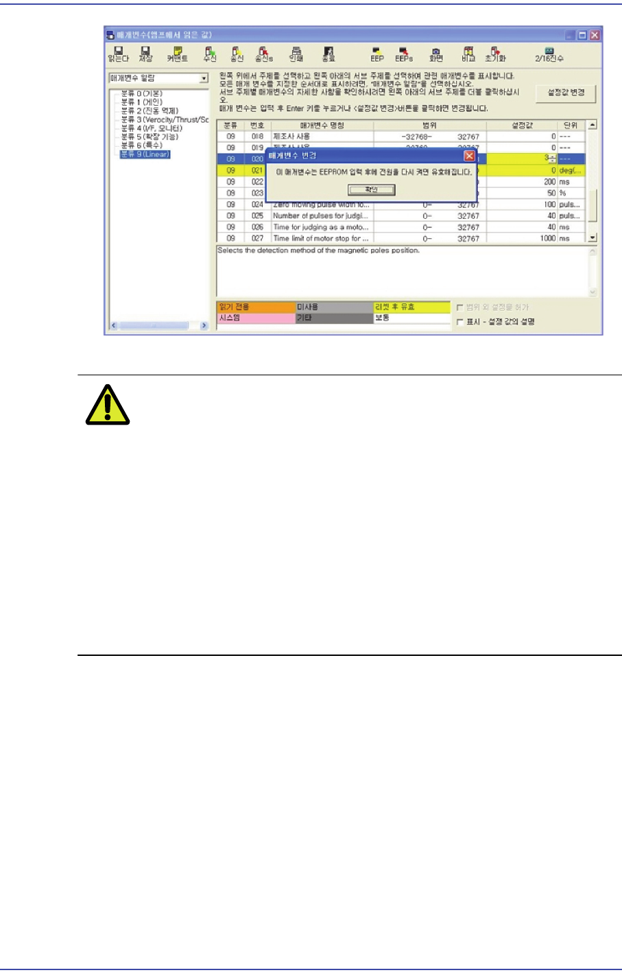
Prerequisite for magnetic estimation:
1: Set the Pr9.20 to 2.
2: Magnetic estimation has never been performed after rebooting
the AMP.
3: The Servo must be turned on.
4: If even one of the above requirements is not satisfied, magnetic
estimation cannot be performed.
12-16
Fast & Flexible Chip Shooter DECAN F2 Service Manual
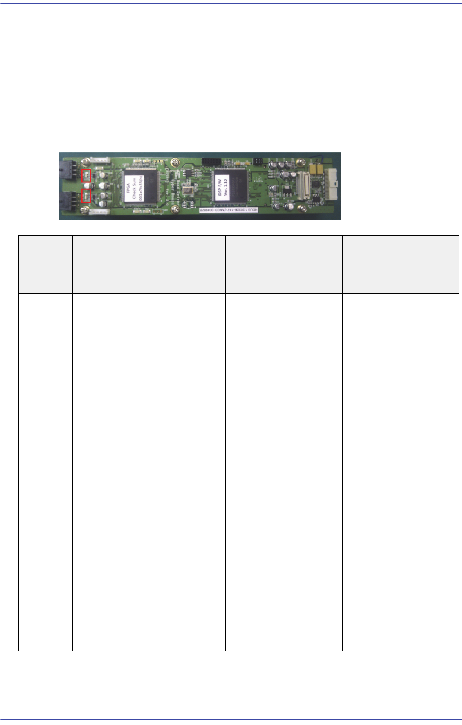
12.5. New Dual Head Amp Driver
12.5.1. Alarm Code
When an error occurs, the 7 segment LEDs of the motor drive will flicker. As well, the
corresponding alarm code is generated. It is of “Err **” form and the “**” will express the
corresponding alarm code.
In this case, take measures against the corresponding alarm code referring to the following
table
Alarm
Code No
Alarm
Content
s
Operating
Condition
Causes Measures
Encoder
Logic
error
1. After applying
the control power.
2: After the main
power is turned on
3. Motor in
operation.
1. Encoder internal
error
2. Driver
communication
between Encoder is
interference, the
communication error
detection function is
executed.
1. Check the Encoder
connector conclusion.
2. Make sure the
Encoder power is
within 5% of DC5V
3. Alarm reset
4. Reset the AMP
power supply.
5. Encoder exchange
Encoder
CRC
error
1. After applying
the control power.
2: After the main
power is turned on
3. Motor in
operation.
1. Communication
error between the
Encoder and FPGA.
2. The data errors due
to poor contact and
noise.
1. Check the Encoder
connector conclusion.
2. Reset the AMP
power supply.
Encoder
Open
error
1. After applying
the control power.
2: After the main
power is turned on
3. Motor in
operation.
1. Communication
error between the
Encoder and FPGA.
2. The data errors due
to poor contact and
noise.
1. Check the Encoder
connector conclusion.
2. Reset the AMP
power supply.

12-17
Motor Driver
Over
Voltage
error
Servo
Amp
Overcurr
ent
Alarm
1. After applying
the control power.
2. Motor in
operation.
1. Problem with the
CT.
2. Problem with the
related circuit.
3. Problem with the
motor.
4. When starting the
Z-axis, any of its
driving mechanism is
stuck.
1. Reset the AMP
power supply.
2. Check the Z-axis
mechanism.
3. Replace the AMP.
Under
Voltage
error
Servo
Amp Low
Current
Alarm
1. After applying
the control power.
2. Motor in
operation.
1. After applying the
control power, the
power DC24V drops
below a specific value.
2. The motor is driven
with a single phase
due to phase lack.
3. 서The circuit is
open and the
regulator damaged.
1. Reset the AMP
power supply.
2. Check the Z-axis
mechanism.
3. Replace the AMP.
Over
Speed
error
The
alarm
against
the
Servo
Amp
started
with
RPM
greater
than the
allowabl
e RPM
Motor in operation. 1. Problem with the
CT.
2. Problem with the
DSP.
3. When starting the
Z-axis, any of its
driving mechanism is
stuck.
1. Check whether the
position offset limit is
inputted.
2. Check the Z-axis
mechanism.
3.Check whether the
encoder connector is
connected.
4. Reset the AMP
power supply.
5. Replace the AMP.
EEPRO
M Check
error
EEPRO
M
Commun
ication
Alarm
After applying the
main power supply
Problem with
communication
between DSP and
EEPROM
1. Reset the AMP
power supply.
2. Replace the AMP.
Alarm
Code No
Alarm
Content
s
Operating
Condition
Causes Measures