DECAN_F2_Service(Eng_Ver1).pdf - 第82页
3-20 Fast & Flexible Chip Shooter DECAN F2 Service Manual 3.2.3. Communication Interfac e Setup between Machines 1) Set the communication interface between th e Previous Machine an d Next Ma chine by referring to the…
3-19
Installation & Operation
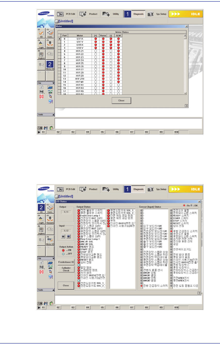
3.2.2. Checking System I/O
1) Select the ‘Diagnosis’ menu in the menu and select submenu ‘I/O’
2) The <Output Status> group at the left of the ‘I/O Status’ dialog box indicates the
machine output.
3) Clicking the list in the <Sensor (Input) Status> group at the right of the ‘I/O Status’
dialog box will turn on/off the input of the corresponding machine and check the input
and output.
3-20
Fast & Flexible Chip Shooter DECAN F2 Service Manual
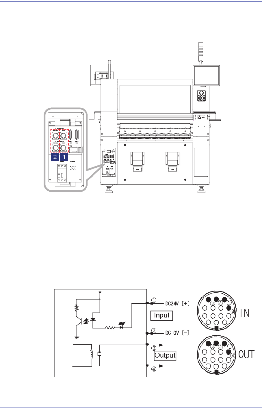
3.2.3. Communication Interface Setup between Machines
1) Set the communication interface between the Previous Machine and Next Machine by
referring to the following.
1: Next Machine
2: Previous Machine
START Input Signal (Cable No.:?(+),?(-))
The input signal is outputted from the next machine and voltage of approximately
20 ~ 22V is measured at most input signal terminals.
READY Output Signal (Cable No.:? , ?)
The output signal is outputted to the previous machine. Generally, at most output
signal terminals, 0 is measured when output signal is outputted and is
measured when output signal is not outputted.
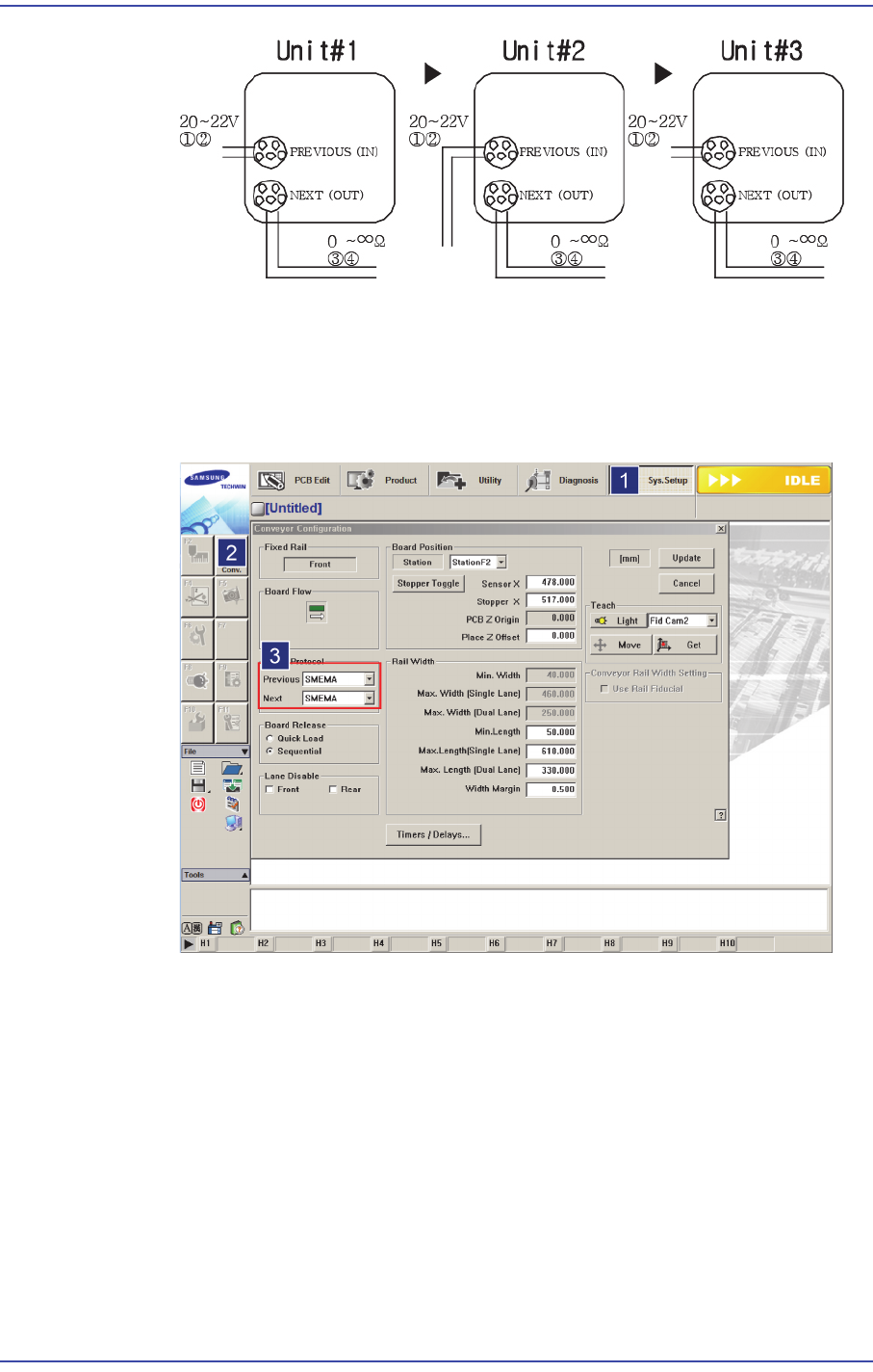
If the I/F connectors of neighboring machines are different, cut the cable and connect
it referring to the following figure.
3-21
Installation & Operation
Machines manufactured not in accordance with the SMEMA code such as SIMENS,
SANYO and TDK (RX-11), and machines without dual contact interface shall be
examined specially.
Machine interface must be decided. (Select 2-contact method or SMEMA method
suitable for the user’s environment.)
Select SYS.SETUP menu and lower menu of the conveyor.
Select ‘Stand Alone’, or SSA Type (2 contacts), or SMEMA in the ‘In (Before)
and Out (After)’ combo box of the inline protocol area.
Stand Alone: The connection is not established between machines. Setup is
made during manual operation.
SSA Type: The PCB flows only if the contact is connected in the next
machine.
SMEMA: The ready signal is given by the previous machine (24V), and the
contact is connected in the next machine.
Check if the interface between connected machines operates normally by using
the MMI bypass function. At this time, perform test using at least 3 pieces of