DECAN_F2_Service(Eng_Ver1).pdf - 第427页
17-15 Troubleshooting E0700 Pause whil e downloading the MMI [Cause] The system file was damage d after being infected by a virus The SBC board is not properly connected to the vision board connector or the vision bo…
17-14
Fast & Flexible Chip Shooter DECAN F2 Service Manual
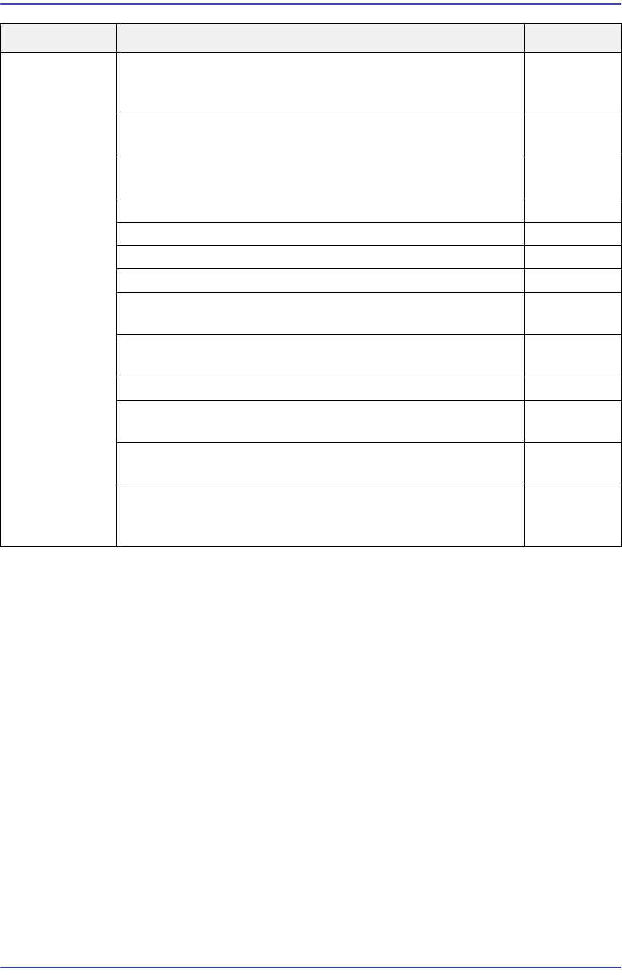
SW Error When booting the machine, the login password input window
is displayed. When a password is inputted, the ‘Incorrect
Password’ message is indicated and Windows is not booted
E7018
The fiducial mark recognition position of the front PCB is
different from that of the rear PCB
E7019
An error indicating the skip count occurred in the Steps
dialog box
E701A
Failed to pick up 0603 chips simultaneously E701B
The PCB file was not downloaded E701C
Head# Dump Limit Error E701D
An error occurred while dumping the connector E701E
The report is not outputted from the ‘Feeder Info.’ dialog box
of the Utility menu
E701F
The machine pauses with the machine being changed into
the 'Run-Ready' state during
E7020
The machine pauses during production E7021
Limitation occurred when exchanging a PCB file between
machines
E7022
A certain part is dumped even when a pickup error did not
occur
E7023
Timeout occurred during Msgdriver (MMI) communication
(Applicable only to SM series machines excluding the SLM/
SM471 machine)
E7024
Cause Description Remarks

17-15
Troubleshooting
E0700 Pause while downloading the MMI
[Cause]
The system file was damaged after being infected by a virus
The SBC board is not properly connected to the vision board connector or the vision
board is not properly inserted into the back plane slot (defective SBC board contact)
The NCIO board is not properly inserted into the back plane board slot
A problem occurred with MMI booting due to a damaged MMI system file
The SBC board, CPU, HDD, etc. are comprehensively defective
The RT and NCIO boards are not properly inserted into the back plane board slot
Defective CPU of the SBC board
[How to Check]
Perform a virus check of the HDD. If it has a problem, perform HDD recovery and
reinstall the MMI. Then check whether the same problem occurs
Remove the SBC board from the back plane board slot. Then insert it properly and
check whether the same problem occurs
Remove the SBC board from the vision board connector and insert it again. Then
remove the vision board from the back plane board slot and insert it again properly and
then check whether the same problem occurs continuously
Check whether the NCIO board is properly inserted into the back plane board slot
Reinstall the MMI and check whether the same problem occurs
Replace the SBC board, CPU and HDD in order and check whether the same problem
occurs to them
Check whether the RT and NCIO boards are properly inserted into the back plane
board slot
Replace the CPU and check whether the same problem occurs
[Measures]
Perform HDD recovery and reinstall the MMI.
Remove the SBC board from the vision board connector and insert it again. Then
remove the vision board from the back plane board slot and insert it again properly.
Insert the NCIO board into the back plane board slot properly.
Reinstall the MMI.
Replace the SBC board, CPU and HDD in order. If the HDD has a problem, perform
HDD recovery after replacing it and reinstall the MMI.
Insert the RT and NCIO boards into the back plane board slots properly.
Replace the CPU.

17-16
Fast & Flexible Chip Shooter DECAN F2 Service Manual
E0701 Ram Ring Error
[Cause]
The cable connecting the PCI I/O board and DPRAM is defective
(Applicable only to SM series machines excluding the DECAN F2, SLM, SM471 and
SM48X.)
A communication error occurred between the CAN Master and the PCI I/O board.
(Applicable only to SM series machines excluding the DECAN F2, SLM, SM471 and
SM48X.)
The PCI I/O board is defective.
(Applicable only to SM series machines excluding the DECAN F2, SLM, SM471 and
SM48X.)
The CAN Master board and MVME 3100 board are defective.
(Applicable only to SM series machines excluding the DECAN F2, SLM, SM471 and
SM48X.)
The Vision board is not inserted into a slot correctly.
(Applicable only to SM series machines excluding SLM471)
[How to Check]
Check whether the cable that connects the PCI I/O board and the DPRAM is correctly
connected.
Remove the PCI I/O board and CAN Master board from the slots and insert them
again and then check whether the same problem occurs.
Replace the PCI I/O board and check whether the same problem occurs.
Replace the CAN Master board and MVME 3100 board and check whether the same
problem occurs.
Remove the Vision board from the slot and insert it into the slot again and then check
whether the same problem occurs.
[Measures]
Check the connection status of the corresponding cable and if there are any problems,
replace the cable connecting the PCI I/O board and DPRAM.
Remove the PCI I/O board and CAN Master board from the slots and insert them
correctly.
Replace the PCI I/O board.
Replace the CAN Master board and MVME 3100 board.
Remove the Vision board from the slot and insert it correctly.