DECAN_F2_Service(Eng_Ver1).pdf - 第78页
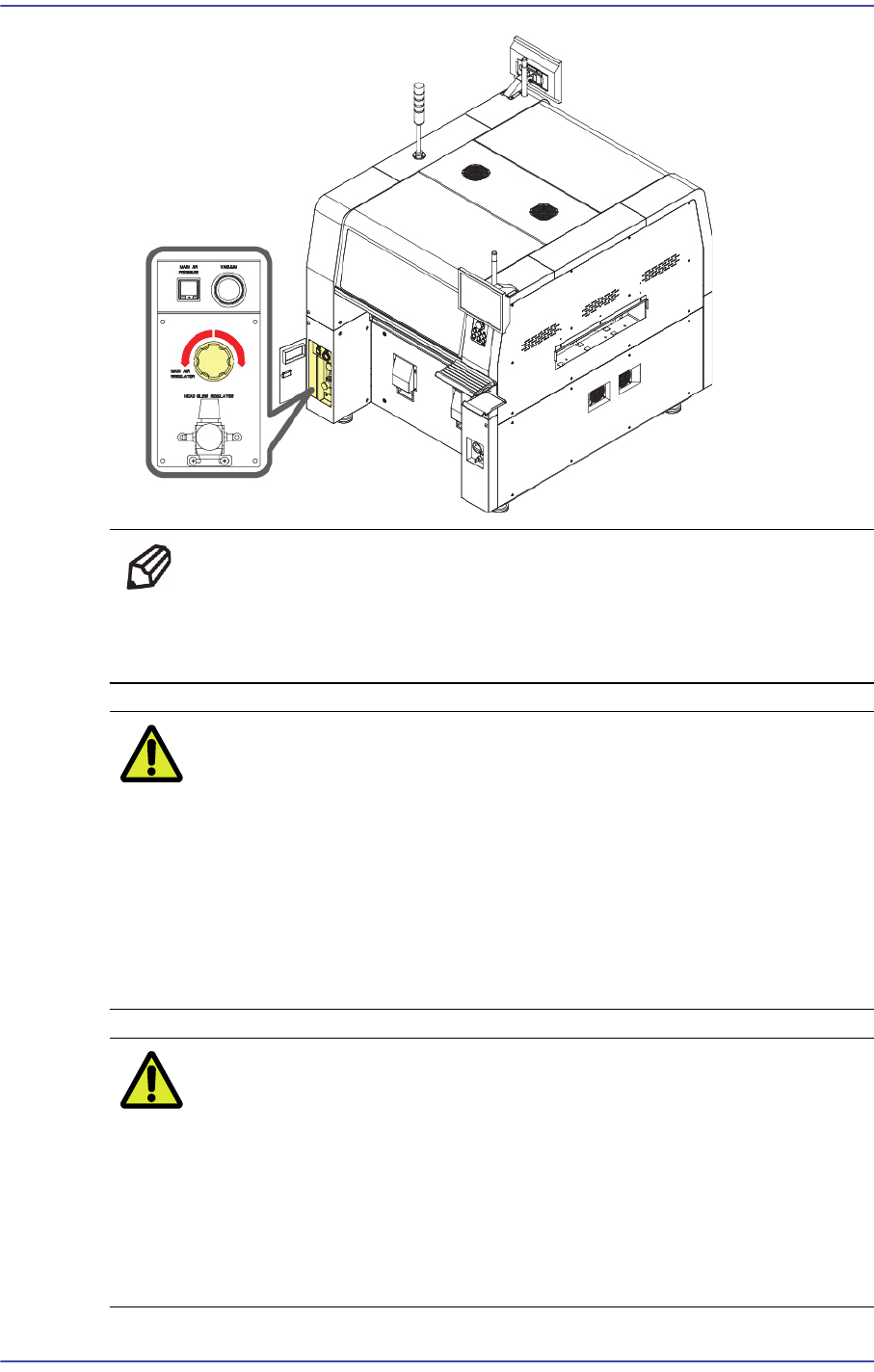
3-16 Fast & Flexible Chip Shooter DECAN F2 Service Manual Ref Counterclockwise regulator ro tation (pressure reduction), Clockwise regulator rotation (pressure increase) Main Regulator: 0.45~0.55 Mpa Caution If t…
3-15
Installation & Operation
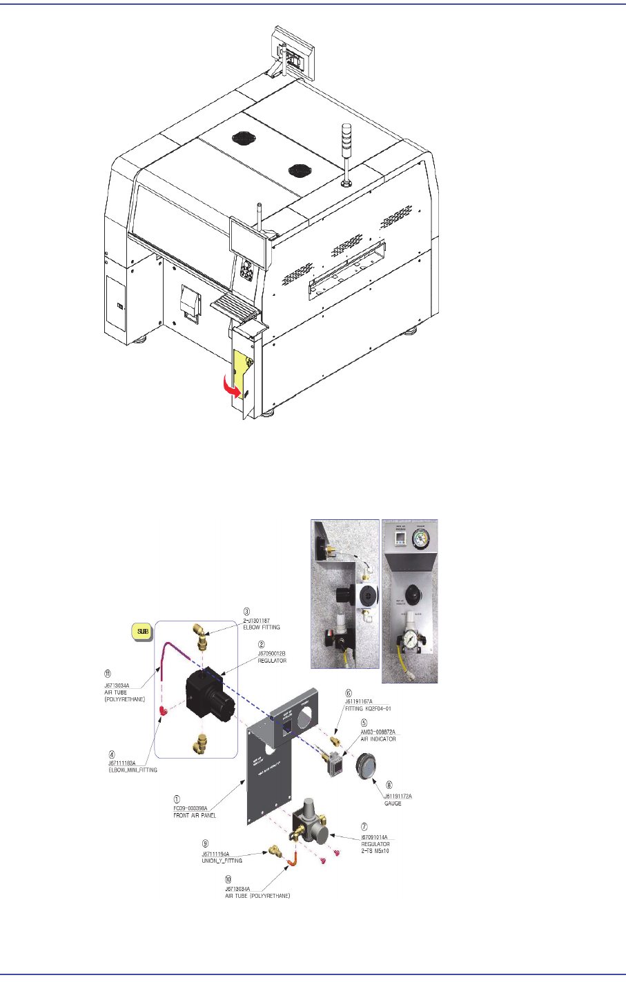
2) Connect pneumatic line to the air main inlet. At this time, check if the air filter and
mist separation filter are installed at the main air connection of the work place where
the machine is to be installed. (If the air pressure is insufficient, the yellow lamp of the
signal light is turned on)
3) Turn the regulator handle to adjust the pneumatic pressure to approximately
0.45~0.55MPa. (The air consumption of the machine is Max. 50 N/min. At this time)
3-16
Fast & Flexible Chip Shooter DECAN F2 Service Manual
Ref Counterclockwise regulator rotation (pressure reduction),
Clockwise regulator rotation (pressure increase)
Main Regulator: 0.45~0.55 Mpa
Caution If the pneumatic pressure is out of the range 0.45 ~ 0.55
Mpa, a problem may occur in part pickup and placement
and feeder movement. Therefore, check the pneumatic
pressure before performing the work.
A compressor with appropriate capacity for the pneumatic
consumption of the machine must be used. Otherwise, the
reduction of the pneumatic pressure in the machine has
influence on the part placement quality.
Caution ?Since foreign materials including chips and burs can be a
problem after installing the pipe, clean the pipe using an air
gun with a clean cloth tied at the pipe end until the cloth that
is replaced after each cleaning becomes clean. Connect the
pipe to the machine when there is no fear of contamination.
Check if an oil filter and air dryer are installed in the air
piping system to prevent condensation.
3-17
Installation & Operation
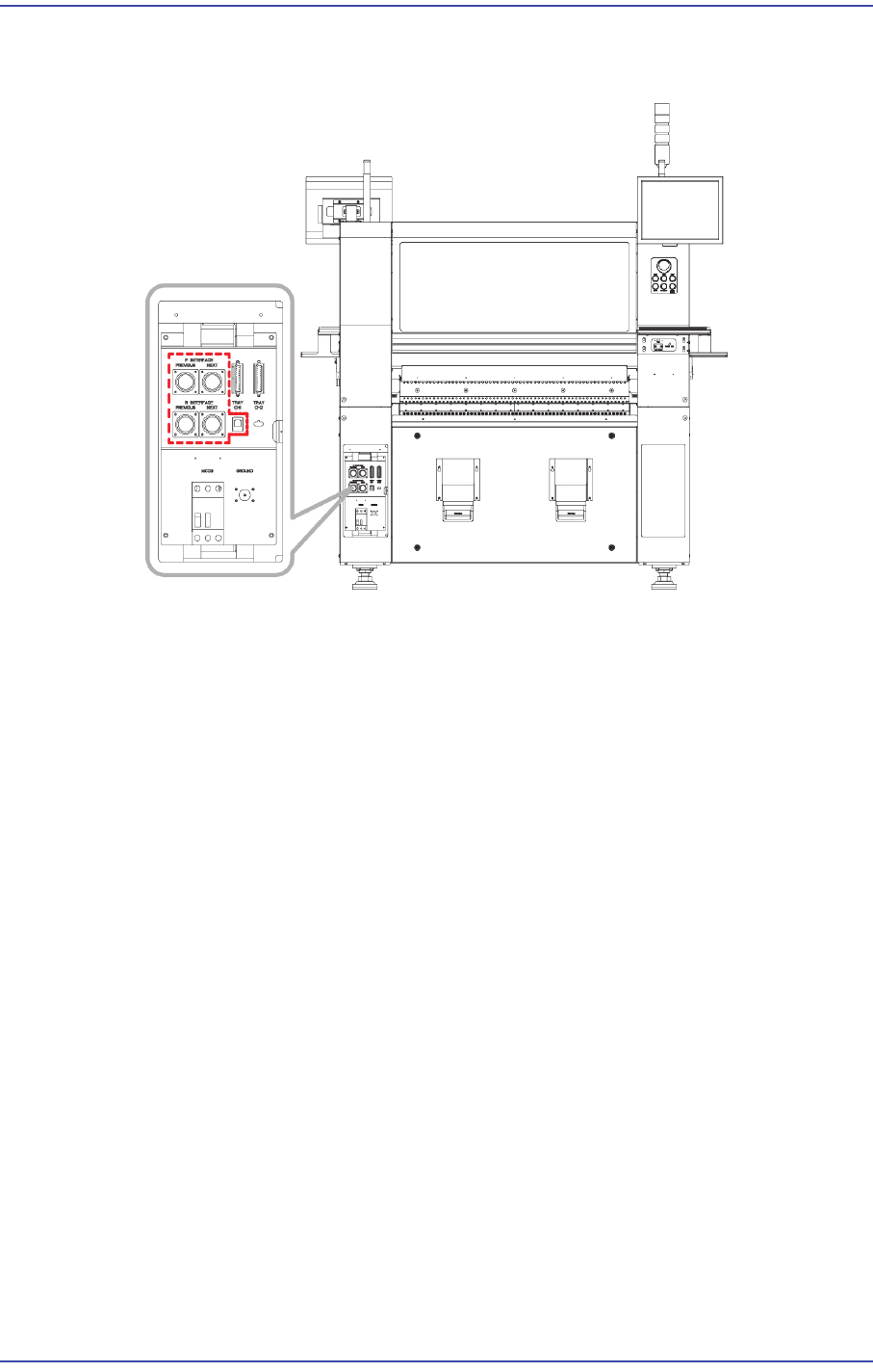
4) Set the communication interface between the printer and chip mounter by referring to
the following.
3.1.7. In-line Installation
The method to adjust level between the machines is as follows.
1) Move the component placer for which setup was already performed to a place near to
the conveyor and lower each foot to adjust the level roughly. At that position, adjust
the level of the machine at approximately 0.1mm/m level.
2) Move the machine by using a lever so that the gap between the conveyor and printer
conveyor that were already installed becomes 3~5mm.
3) Adjust the machine level again. (Refer to the previous leveling procedure)
4) Perform setup after placing the PCB on both the buffer conveyor and the conveyor for
the printing machine. Set the level difference between machines to 0.05~0.50mm
based on the ‘Down Flow’ in the direction in which the PCB flows so that the PCB
flows downward.
5) In order to adjust the straightness of PCB flow between machines, make each PCB
contact with the conveyor fixing frame and install the conveyor so that there will be no
gap between PCBs at the front and rear sides of the PCB.