DECAN_F2_Service(Eng_Ver1).pdf - 第487页
17-75 Troubleshooting 17.3.11. Defective operation of OP panel, teaching box and door switches (E0F) E0F00 OP The OP Panel Switch does not work properly (LED not turned on, etc.) [Cause] The panel switch itself is defe…

17-74
Fast & Flexible Chip Shooter DECAN F2 Service Manual
E0E06 The feeder is not removed and installed smoothly
[Cause]
Defective machine of the feeder base hole
[How to Check]
1. The feeder is installed and removed stiffly.
2. Check the external shape of the feeder.
3. Replace the feeder base.
[Measures]
Replace the feeder base.
E0E07 Failed to move up the front docking cart
[Cause]
The D-CART Probe Pin is damaged.
[How to Check]
Replace the D-CART Inner I/F cable assembly.
[Measures]
Replace the D-CART Inner I/F cable assembly.
E0E08 Only one part in the vibration feeder is continuously picked up
[Cause]
The feeder is used with its link function being cleared.
[How to Check]
Set the ‘Successive Link’ function of the ‘Stick Auto Link Opt’ in the system.
[Measures]
Set the ‘Successive Link’ function of the ‘Stick Auto Link Opt’ in the system.
E0E09 The [Open Error] of the Feeder Part $P Clamp is cleared. (Vibration feeder Index is
defective)
[Cause]
The white pin is disconnected (disconnected inside the shield).
[How to Check]
1. Check the operation of the vibration feeder.
2. Check the probe pin of the vibration feeder.
3. Check the inner board and connector of the vibration feeder.
[Measures]
Solder and connect the disconnected pin.
17-75
Troubleshooting
17.3.11. Defective operation of OP panel, teaching box and door switches (E0F)
E0F00 OP The OP Panel Switch does not work properly (LED not turned on, etc.)
[Cause]
The panel switch itself is defective.
[How to Check]
1. Check the OP Panel Switch input in the MMI.
2. Replace the corresponding switch and LED.
[Measures]
Replace the switch or LED.
E0F01 Front/Rear Teaching Box or OP Switch cannot be operated
[Cause]
The F/R Operate Board is defective.
The teaching box is defective.
The PMC NVRAM board is defective.
(Applicable only to SM series machines excluding DECAN F2, SLM, SM471 and
SM48X)
Defective contact of the F/R Operate Board
Defective contact of the CAN Conveyor Board connector
Defective contact of the NVRAM Board
(Applicable only to SM series machines excluding the DECAN F2, SLM, SM471 and
SM48X.)
[How to Check]
1. Check the Select Switch LED on the F/R panel (LED On/Off, I/O operation).
2. Check the teaching box operation state.
3. Replace the F/R Operate Board.
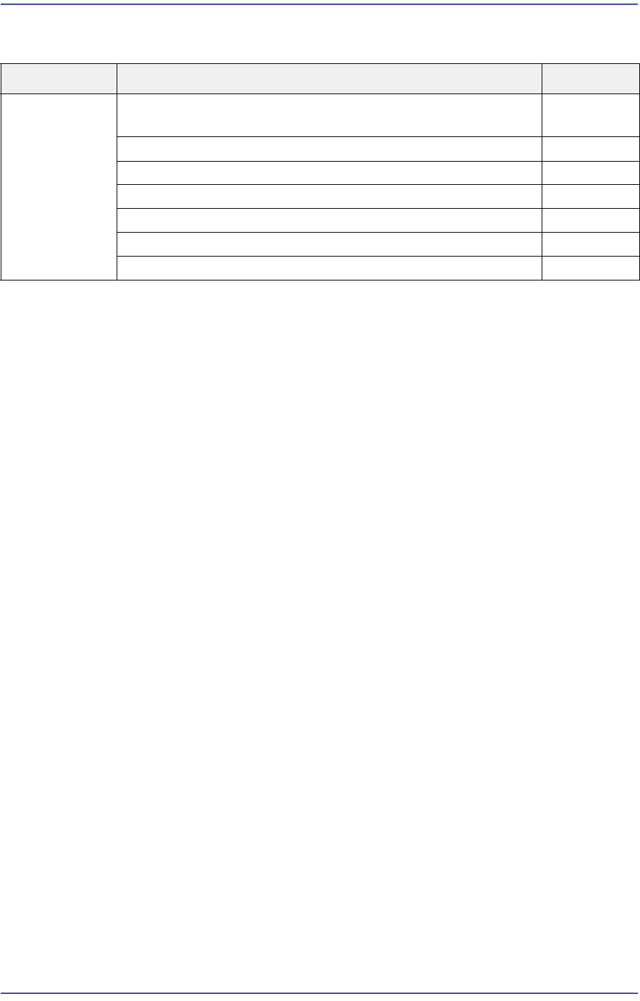
Cause Description Remarks
Defective
operation of
OP panel,
teaching box
and door
switches
The OP Panel Switch does not work properly (LED not turned
on, etc.)
E0F00
Front/Rear Teaching Box or OP Switch cannot be operated E0F01
F/R keyboard or mouse does not work E0F02
Recognition error of the keyboard, mouse and USB memory E0F03
The Motor Free switch of the teaching box is pressed E0F04
No response when opening the door E0F05
Ready Off when opening the door E0F06

17-76
Fast & Flexible Chip Shooter DECAN F2 Service Manual
4. Replace the SBC Board.
1. Check whether the MVME Board is defective.
2. Replace the MVME Board.
3. Replace the PMC NVRAM Board.
1. Check the Select Switch LED of the F/R panel (LED On/Off, I/O operation).
2. Check the teaching box operation state.
3. Replace the F/R Operate Board.
4. Replace the SBC Board.
1. 24V power supply of the CAN Conveyor Board.
- Check the input state (LED On)
- Replace the Power Supply #1.
2. Check and replace the CAN Conveyor Board.
1. Check whether the MVME Board is defective.
2. Replace the MVME Board.
3. Replace the PMC NVRAM Board.
[Measures]
Replace the F/R Operate Board.
Replace the teaching box.
Replace the PMC_NVRAM_Board.
Reassemble the F/R Operate Board.
Reassemble the CN28 connector of the CAN Conveyor Board.
Reassemble the NVRAM Board.
E0F02 F/R key board or mouse does not work
[Cause]
Defective contact of the USB cable (PC Rack, Front Cover)
Defective USB cable
Defective keyboard or mouse
Incorrect CMOS USB 2.0 setting
[How to Check]
1. Check the operation state of the F/R keyboard and mouse.
2. Check the CMOS USB setup.
3. Check the power supply and contact state of the external USB port.
[Measures]