DECAN_F2_Service(Eng_Ver1).pdf - 第185页
7-3 ANC 7.2. Shutter Cylinder 7.2.1. Required Tools T W rench (other tools supplied) or Hex W rench T orque W rench 7.2.2. Shutter Cylinder Replacement Procedure 1) Manipulate t he teaching box to perform homing (Ret…
7-2
Fast & Flexible Chip Shooter DECAN F2 Service Manual
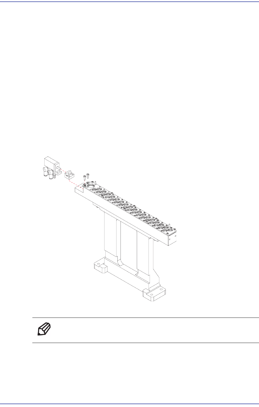
4) When assembling it with a new ANC Module, refer to the following.
When assembling the ANC, secure a parallelism of 0.02mm between the X Gantry
and ANC.
1. Set the parallelism by attaching the Magnetic Indicator (minimum scale 2?) to
the head tip.
2. If Step #1 above cannot be performed, set the parallelism while watching the
ANC fiducial mark and Vision window using the fiducial camera on the head.
7-3
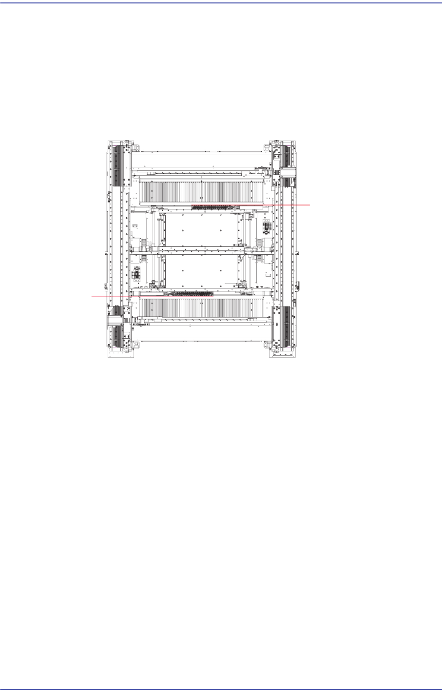
ANC
7.2. Shutter Cylinder
7.2.1. Required Tools
T Wrench (other tools supplied) or Hex Wrench
Torque Wrench
7.2.2. Shutter Cylinder Replacement Procedure
1) Manipulate the teaching box to perform homing (Return to Origin) of the machine.
2) Turn Off the PC in normal way. Then turn off the main switch on the front side of the
machine.
3) Please shut off the main Pneumatic of the device.
4) Please remove the Pneumatic that is connected to the Cylinder.
5) Unscrew the fixing bolts (2-M3*8) securing the Cylinder using a wrench and remove
it.
6) Assemble in the ANC Module a new Cylinder.
Ref The part number of the new Cylinder is J6701029A.
7) Turn on the main switch at the front of the machine and boot the PC once the
replacement is completed.
7-4
Fast & Flexible Chip Shooter DECAN F2 Service Manual
7.3. ANC Shutter
7.3.1. Shutter Speed Adjustment
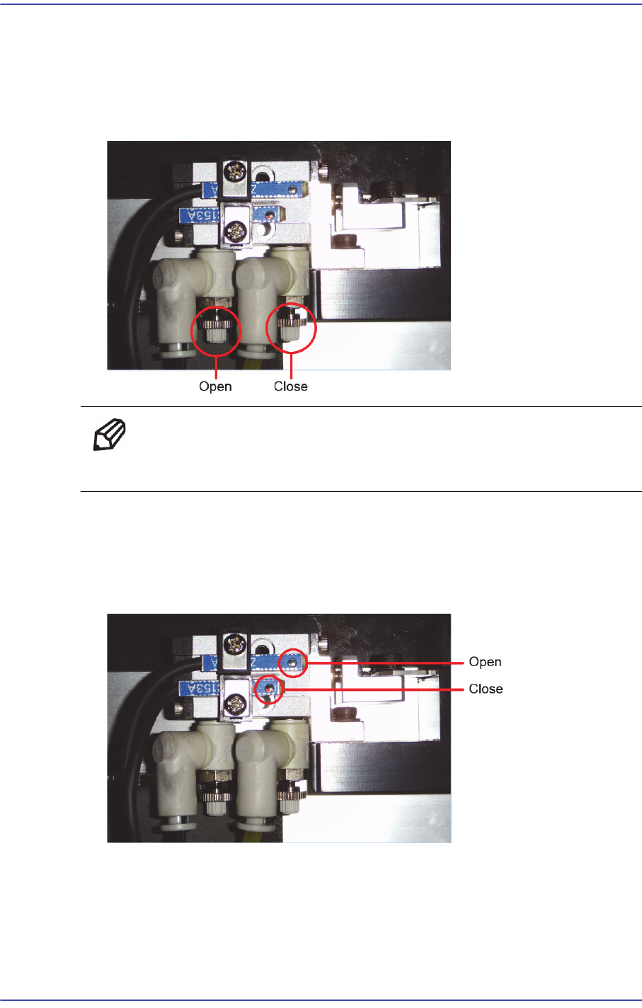
1) Adjust the speed controller to control the closing and opening speed of the shutter
while moving the shutter.
Ref Turning the speed controller clockwise will reduce the speed and
turning it counterclockwise will increase the speed.
7.3.2. Assembly and method of operation check Shutter Sensor
1) Leave the shutter closed and check the detection range by checking if the sensor is
turned on/off while moving the ‘Close’ detection sensor. (Lower side sensor)
2) Assemble the sensor by moving it by 1mm to the left from the right end of the ‘Close’
detection sensor within the detection range.