DECAN_F2_Service(Eng_Ver1).pdf - 第154页
6-4 Fast & Flexible Chip Shooter DECAN F2 Service Manual 6.2. Belt 6.2.1. Required Tools T ension Gage (U-50 5) U-505 Jig T W renc h (other tools supplied) or Hex W rench Gear wrench C-Ring T ool 6.2.2. Bel…

6-3
Conveyor
Ref The part number of the new width sensor is J3212002A.
6) Assembled the reverse order of disassembling.
7) Turn on the main switch at the front of the machine and boot the PC once the
replacement is completed.
8) Move the Conveyor Move Frame to check whether the replaced sensor performs
detection properly.
9) Perform the following calibrations.
Board Position Calibration
(Time: 5Minute/1 Module)
6-4
Fast & Flexible Chip Shooter DECAN F2 Service Manual
6.2. Belt
6.2.1. Required Tools
Tension Gage (U-505)
U-505 Jig
T Wrench (other tools supplied) or Hex Wrench
Gear wrench
C-Ring Tool
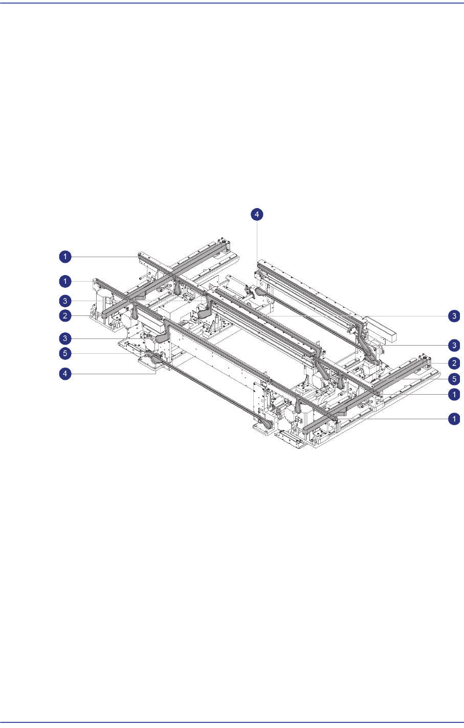
6.2.2. Belt
1: Entry / Exit Zone PCB Transfer Belt
2: Entry / Exit Zone width adjustment Belt
3: Work Zone PCB Transfer Belt
4: Work Zone width adjustment Belt
5: Work Zone Power transmission Belt
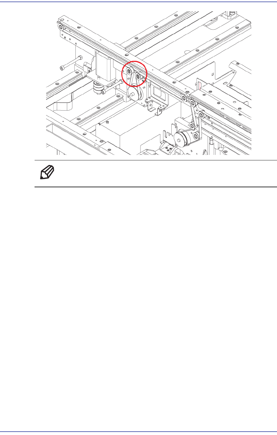
6.2.3. Entry / Exit Zone PCB Transfer Belt Replacement Procedure
1) Manipulate to increase the conveyor width as wide as possible.
2) Close the PC as usual and turn off the main switch at the front of the machine.
3) Remove the Belt to reduce the Tension Loosen slightly the Idler Shaft Belt of the
attempt to replace.
6-5
Conveyor
Ref The part number of the belt is MC05-000068A.
4) When assembling it with a new Belt, refer to the following.