DECAN_F2_Service(Eng_Ver1).pdf - 第349页
14-9 Board Ref When the power supply is short- circuited, the green LED blinks. Therefore, turn the power supp ly off and check the circuit. 14.1.6. SSD Replac ement Procedure 1) Remove the mo ther board among CPU boards…
14-8
Fast & Flexible Chip Shooter DECAN F2 Service Manual
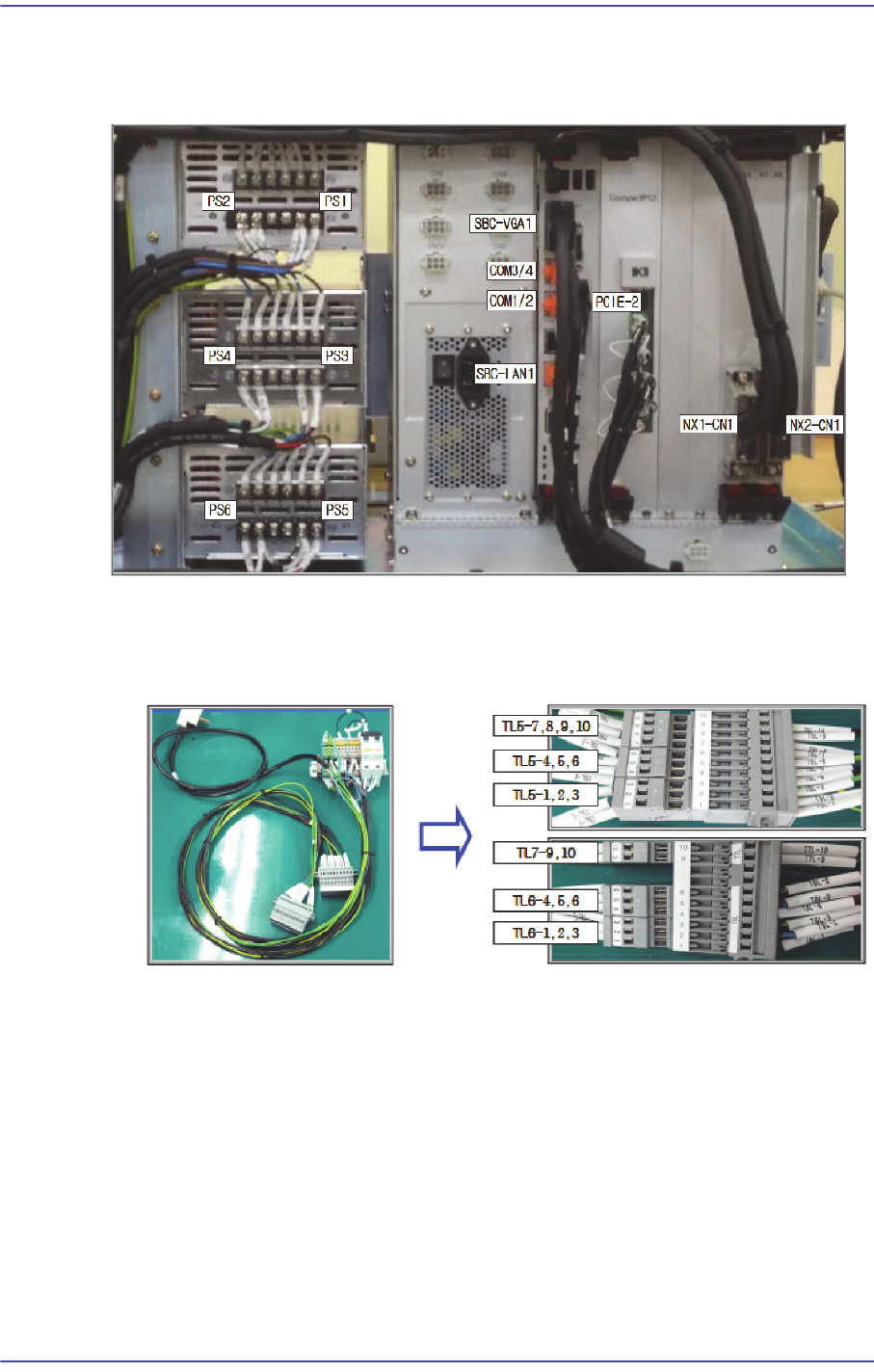
14.1.5. Cable connection of PC Rack
14.1.5.1. View of cable whose connection is completed
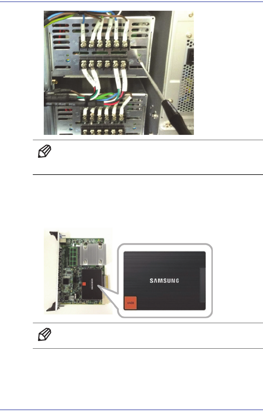
14.1.5.2. Power Test method
1) Connect the inspection jig and PC rack.
2) Set the power supply as shown in the following figure.
14-9
Board
Ref When the power supply is short-circuited, the green LED blinks.
Therefore, turn the power supply off and check the circuit.
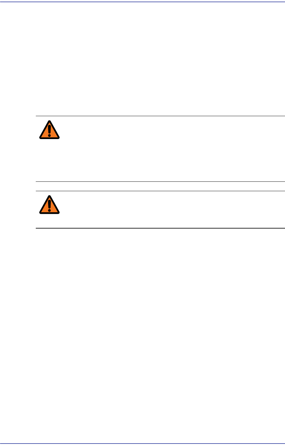
14.1.6. SSD Replacement Procedure
1) Remove the mother board among CPU boards.
2) Remove and replace the SSD of the mother board.
Ref The part number of the new SSD is CD05-000050.
3) Assemble it in the reverse order of disassembling.
14-10
Fast & Flexible Chip Shooter DECAN F2 Service Manual
14.2. Head
14.2.1. Required Tools
Crosshead (Phillips) screwdriver and flathead screwdriver
T Wrench or Hex Wrench
14.2.2. Head IF Board Replacement Procedure
1) Close the PC as usual and turn off the main switch at the front of the machine.
2) Turn off the main power supply to the machine.
Warning Before servicing the machine, turn off the power switch
located at the front bottom as well as the main circuit
breaker at the rear bottom of the machine. Otherwise,
serious personal injury may occur. Perform servicing with
the power supply to the machine cut off without fail.
Warning Be sure to wear anti-electrostatic gloves when servicing the
machine.
3) Move the head module forward.
4) Unscrew the fixing bolts securing the head top cover and remove it.