DECAN_F2_Service(Eng_Ver1).pdf - 第64页
3-2 Fast & Flexible Chip Shooter DECAN F2 Service Manual W rench set, wrench drill 3.1.2.2. Unpacking Procedure 1) Remove the external c arton box and steel packing material. 2) Check if the quantity of the spare p…

3-1
Installation & Operation
Chapter3. Installation & Operation
When installing the machine newly, observe the following procedure.
Warning Installation or startup by an inexperienced operator may
damage the machine or cause injury. The installation or
startup operation must be performed by our designated C/S
personnel.
3.1. Machine Installation
3.1.1. Unloading Machine
3.1.1.1. Required Tools
Forklift
Safety fence
3.1.1.2. Unloading Procedure
1) Personnel in charge of installation and commissioning must check details of shipment
with the Production Management Department and inform the customer of the expected
arrival time before leaving for the installation site.
2) After arriving at the site, perform visual inspection of the exterior of the machine
before unloading it. (check for crushing of the box, etc.)
3) Check safety related items before unloading the machine. Perform safety measures by
installing safety fence, etc., if necessary. (Example: working in a high location.)
4) The personnel of the Business Department shall receive the delivery certificate and
forms from the operator and check the state and quantity of the machines before
signing the delivery forms and then finishes the machine delivery and acceptance
procedure with the operator.
5) When unloading the machine, provide instructions so that the machine is not damaged
by forklift and ensure the subcontractors responsible for unloading and transportation
understand the precautions to be observed when handling weak parts of the machine.
Then unload the machine using the corresponding jigs and devices. Unload the
machine only by using a forklift.
3.1.2. Unpacking Transportation
3.1.2.1. Required Tools
Forklift and hand lift
3-2
Fast & Flexible Chip Shooter DECAN F2 Service Manual
Wrench set, wrench drill
3.1.2.2. Unpacking Procedure
1) Remove the external carton box and steel packing material.
2) Check if the quantity of the spare parts in the spare part list is the same as the number
of spare part packing boxes.
3) Move the machine’s components to the location where the machine is to be installed.
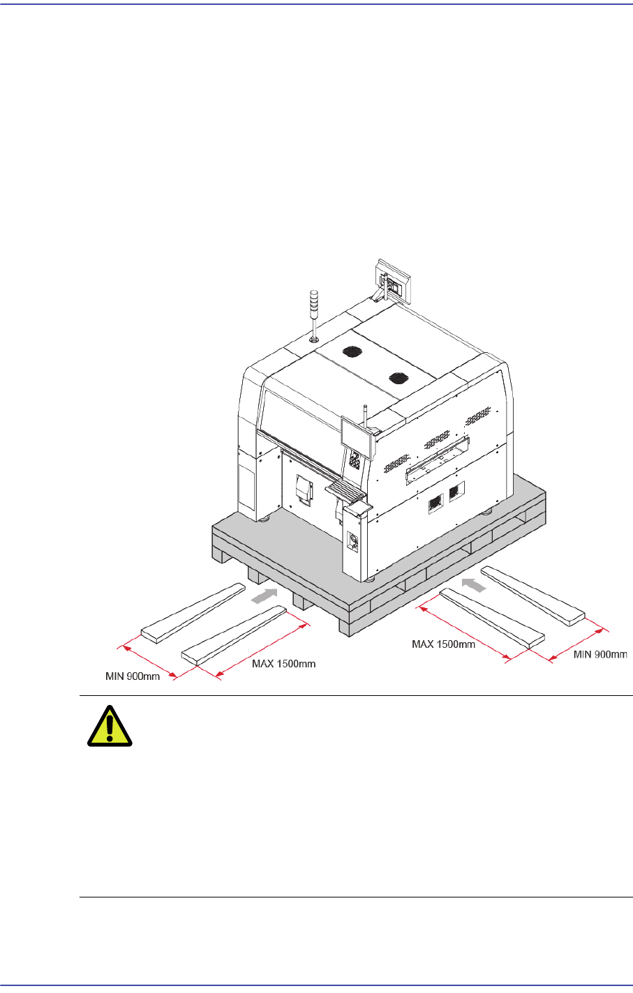
4) Adjust the lift width of the forklift referring to the following figure and move the
machine.
Caution The upper surface of the lift arm must contact the flat
section of the pallet.
In addition, check the position of the lift arm (fork) to prevent
the machine from inclining and the foot or caster of the
machine from being damaged.
When performing work at the front, use a lift arm (fork)
greater than a minimum of 1500mm in size.
5) When transporting the machine to the designated location after unloading the machine
from the pallet, raise the feet of the machine completely and move it using a hand lift.
3-3
Installation & Operation
Caution If the machine is installed on the floor made of shock-
absorbing material or wood that is not strong, excessive
vibration may occur during operation. Be sure to install the
machine on the strong and solid floor.
6) Install the machine that was move to the designated place after confirming the place of
the installation line from the responsible personnel of the customer.
7) Remove the vinyl sheet, internal packing material and desiccant.
Caution If the machine is unpacked by imposing excessive impact
on it, the machine cover may be damaged. Do not unpack
the machine by imposing excessive impact on it. .
3.1.3. Machine Installation
3.1.3.1. Required Tools
Leveler 4 sets (Specification: Leveler with accuracy higher than 0.02mm/m)
It is easy to use a leveler with an accuracy of 0.02 mm/m and 100 x 18 x 55 mm in
size.
Gear wrench for leveling (2 sets)
Vernier calipers
Crosshead (Phillips) screwdriver
Tester
Caution The approved and calibrated leveler must be used. Its
approval and calibration cycle is 1 year.
3.1.3.2. Installation Procedure of Stand-alone Machine
1) When installing the machine in the In-line system, adjust each foot to match the
conveyor reference surface with the previous and following machines. Align the
reference surface between machines within 0.05mm from the left and right. Remove
the front and rear covers before adjusting the height
2) Set the reference level of the machine to 900mm and 950mm based on the conveyor
surface (European standard, CE). However, a deviation of 0 ~ ±15 mm is allowed
depending on the condition (inclination) of the floor’s surface.