DECAN_F2_Service(Eng_Ver1).pdf - 第523页
18-3 Machine Calibration Used for moving the selecte d object to the assigned position of coordinates by rotating XY , Z axis driving motor , or for obtaining the present coordinates of the selected o bject. Fid Cam2: …

18-2
Fast & Flexible Chip Shooter DECAN F2 Service Manual
The value “53.0” refers to the default value applied to this machine, which means
the position where the component is aligned on the top surface of the PCB.
<Use> column
Determines whether to use a head or not. If an error occurs concerning the head,
remove the selected head. However, in order to reassign the work assigned to the
corresponding head, execute the optimizer program again.
<Vac.Level> column
Indicates the pneumatic pressure level of the head with no nozzle set currently. If
necessary, the currently set value can be changed by inputting the pneumatic
pressure level of the head.
The base value is 160 and if the corresponding value exists between 100 and 220,
it is considered that the pneumatic system has no problem.
<Vac.Delay> column
Used to set the Vacuum Delay differently by heads. If a certain head cannot
perform work properly with a normal Delay due to a solenoid problem, input a
specific Delay value in the <Vac. Delay> column of the corresponding head. The
corresponding head then applies the Vacuum Delay with a higher priority than the
Vacuum Delay set during part registration to perform the work.
<Set Nozzle Vacuum> group
Measures the pneumatic pressure level of each head and indicates it in the
<Vac.Level> in the <Grid> group. Before clicking this button, the nozzles inserted
into the nozzle holder of each head must be removed first.
<Head Block Wait Position> group
Set the waiting position for the head assembly. To change the presently setup position,
newly teach the corresponding position.
<When Front feeder change button pressed> edit box
When the “Front feeder change” button on the front operation panel of the
machine is pressed, set the waiting position for the head assembly.
<When Rear feeder change button pressed> edit box
When the “Rear feeder change” button on the rear operation panel of the machine
is pressed, set the waiting position for the head assembly.
<Calibration Position> edit box
When performing calibration, set the position at which the head assembly waits.
<Gantry> Combo Box
Select the gantry for which setups related to head are to be performed.
<Teach> group
<Device> combo box

18-3
Machine Calibration
Used for moving the selected object to the assigned position of coordinates by
rotating XY, Z axis driving motor, or for obtaining the present coordinates of the
selected object.
Fid Cam2: Select the Fiducial Camera2 on the front gantry.
Fid Cam4: Select the Fiducial Camera4 on the rear gantry.
Head 1 ~ Head 20: Select #1 ~ #20 heads.
<Move> button
Move the object selected in the combo box to the position of the assigned
coordinates. At this time, before executing <Move> button, the edit box
corresponding to the desired position must be clicked on with a mouse.
<Get> button
Obtain coordinates for XY, Z axis with reference to the object selected in the
<Device> combo box. At this time, before executing <Get> button, the edit box
corresponding to the desired position must be clicked on with a mouse.
<Update> button
Transmits the set data to the machine and closes the dialog box.
<Cancel> button
Ignores the set data and closes the dialog box.
18-4
Fast & Flexible Chip Shooter DECAN F2 Service Manual
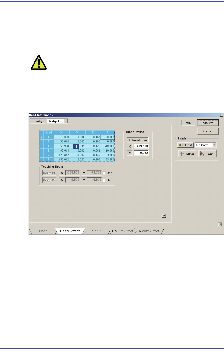
18.1.2. <Head Offset> Tap dialog box
Setup the offset for the mechanical characteristics of each head. The head offset
information displayed here, with the exception of that for the Z and R axes is updated
automatically if the head offset calibration is executed during camera calibration and the
result value is reflected.
Caution Do not modify data in the actual placement of each head at
user’s discretion, as damage to head or defective work may
occur if the setup value has changed by the user when
placement is being performed based on the offset value.
Figure18.2 “Head Offset” tab dialog
1: Grid group
<Gantry> combo box
Selects the gantry for which setup will be performed.
<Grid> group
Sets the offset between heads.
<Head> column
Displays the head number.
<X> column
Sets the X offset value. Set the X position of the head1 to 0 when the XY axes
reach home and set this value as a reference.