DECAN_F2_Service(Eng_Ver1).pdf - 第132页
5-32 Fast & Flexible Chip Shooter DECAN F2 Service Manual Ref The part number of the new motor is EP08-00 0007. 1 1) When assembling, refer to the following. Assemble the pulley to the motor at 6.1mm intervals. T…
5-31
Head
Ref The part number of the new sensor is J32121021A.
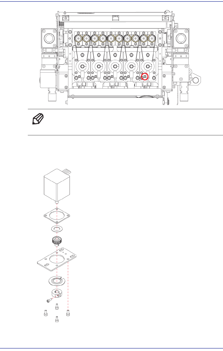
9) When replacing the motor, continue the following procedure.
10) Unscrew the fixing bolts (M2*6) securing Pulley and remove it. Then unscrew the
fixing bolts (4-M2.5*6) securing Motor and remove it.
5-32
Fast & Flexible Chip Shooter DECAN F2 Service Manual
Ref The part number of the new motor is EP08-000007.
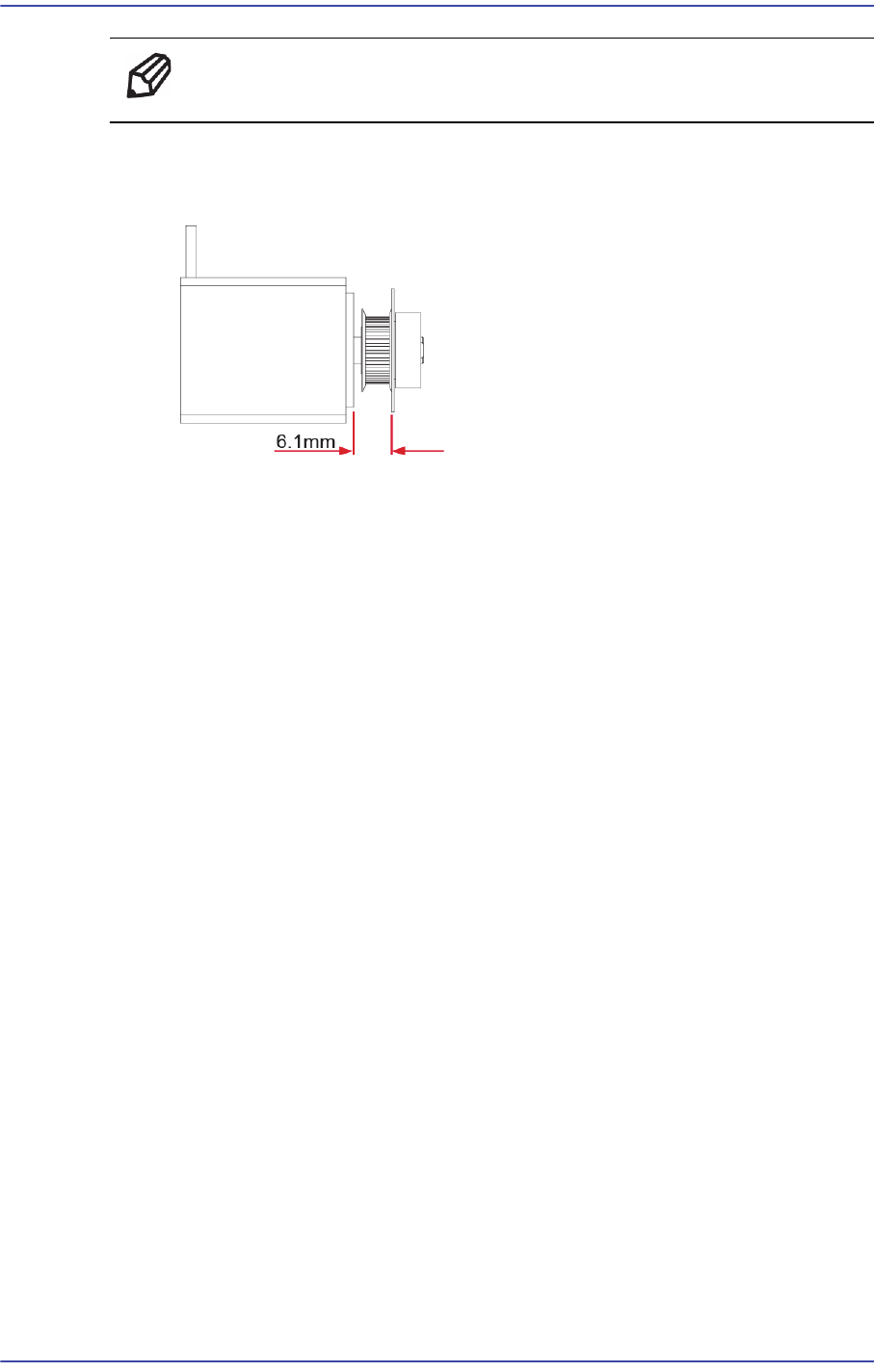
11) When assembling, refer to the following.
Assemble the pulley to the motor at 6.1mm intervals.
The pulley tightening torque is 4kgf-cm.
12) Once the assembling is completed, turn on the main switch on the front of the machine
and boot the PC.
5-33
Head
5.8.3. How to replace the R-axis sensor individually
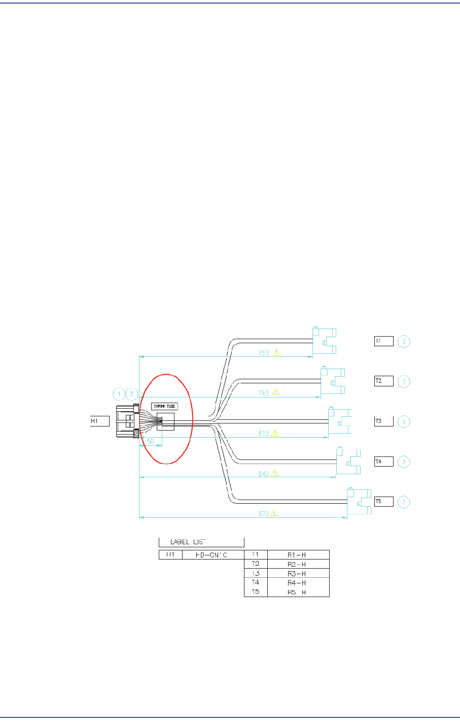
1) Remove the R-axis home sensor cable from the machine as shown in Figure 1.
After removing the CN10 connector of the Head IF board, remove the R-axis home
sensors (5 sets).
2) Remove the area treated with a shrink tube as shown in Figure 1.
3) Replace the R-axis home sensor.
R1 Home Sensor: Connect the sensor to A1/A4/B4 referring to Figure 2.
R2 Home Sensor: Connect the sensor to A2/A5/B5 correctly referring to Figure 2.
R3 Home Sensor: Connect the sensor to A3/A6/B6 correctly referring to Figure 2.
R4 Home Sensor: Connect the sensor to A2/B1/B5 correctly referring to Figure 2.
R5 Home Sensor: Connect the sensor to A3/B2/B6 correctly referring to Figure 2.
4) After replacing the Z-axis sensor, finish the area where the connector and cable is
connected and then they are treated with a shrink tube by using insulation tape so that
current does not leak out.
5) After replacing the sensor, connect the connector to the Head I/F board and connect
the Z-axis home sensors (5 sets) to the head spindle again.
R Axis Home Sensor Cable