DECAN_F2_Service(Eng_Ver1).pdf - 第113页
5-13 Head 5.4. Flying Illumination Unit 5.4.1. Required Tools T wrench (other tools supplied) or hex wrench Gear wrench or torque wrenc h 5.4.2. Outer A Illuminati on Replacement Procedure 1) Manipulat e the teaching…
5-12
Fast & Flexible Chip Shooter DECAN F2 Service Manual
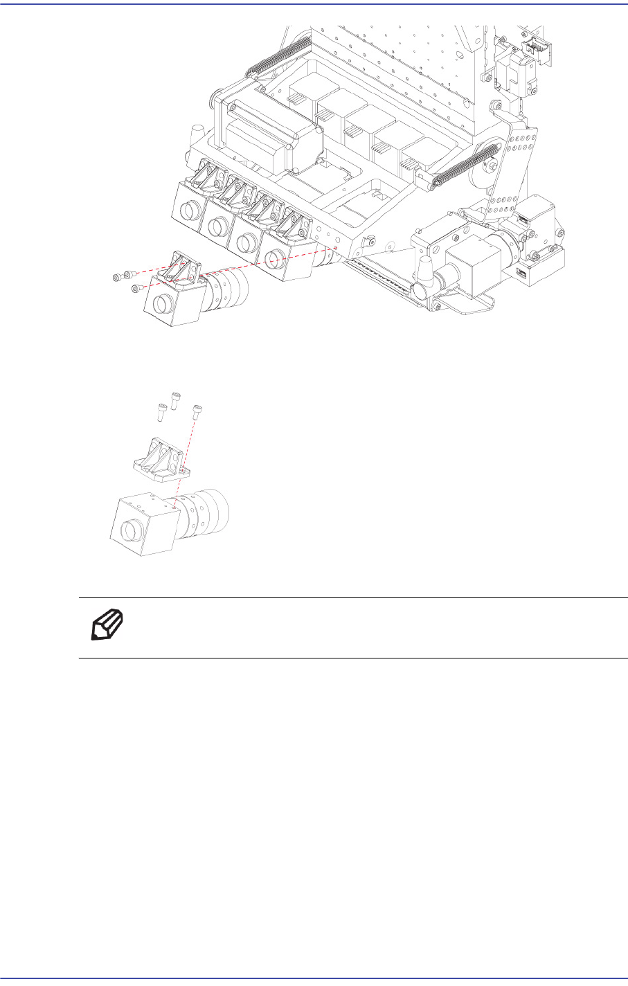
7) Unscrew the fixing bolts(3-M2*6) securing the camera using a hex wrench and
remove it.
8) Replace the Camera with a new one.
Ref The part number of the new Camera is J91851018A.
9) Assemble the board in the reverse order of disassembling.
10) Once the assembling is completed, turn on the main switch on the front of the machine
and boot the PC.
11) Perform the following calibrations.
Camera Offset Calibration
Head Z & R Offset calibration
Light Mapping
Total Time : 1Hour
5-13
Head
5.4. Flying Illumination Unit
5.4.1. Required Tools
T wrench (other tools supplied) or hex wrench
Gear wrench or torque wrench
5.4.2. Outer A Illumination Replacement Procedure
1) Manipulate the teaching box to move the head module to the front.
2) Close the PC as usual and turn off the main switch at the front of the machine.
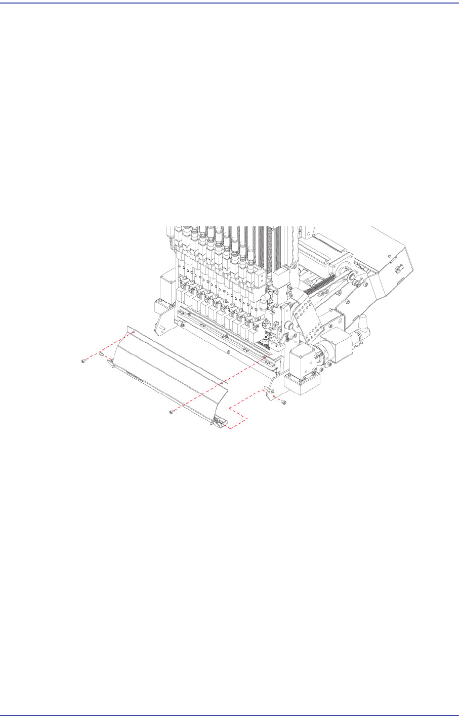
3) Remove the connectors connected to the Outer A PCB.
4) Unscrew the fixing bolts(4-M2*4) securing the Outer A Assy and remove it.
5-14
Fast & Flexible Chip Shooter DECAN F2 Service Manual
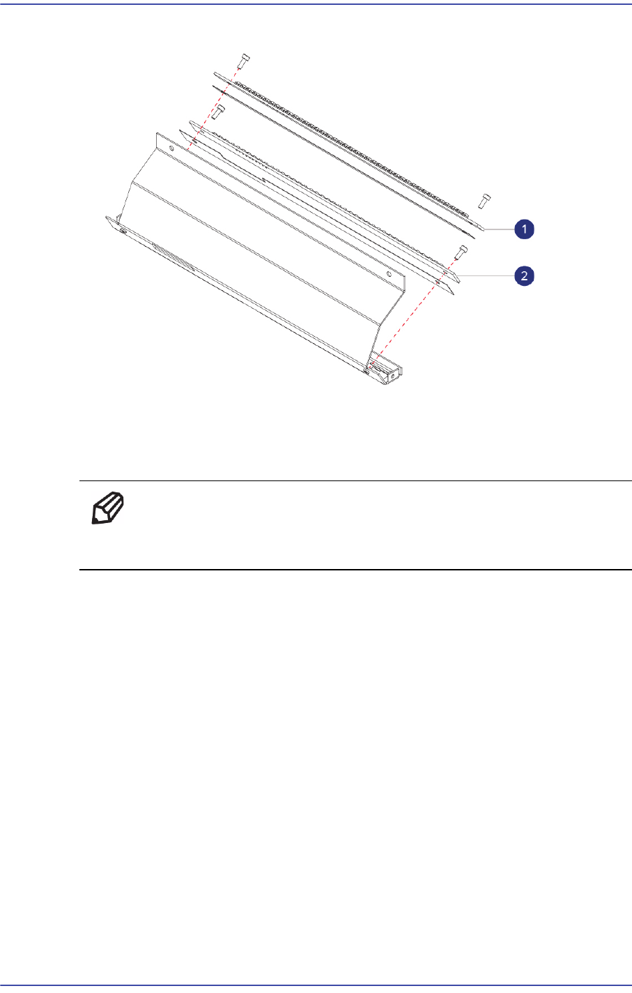
5) Unscrew the fixing bolts(4-M2*6) securing Outer A PCB and remove it.
1: Outer PCB A
2: Outer PCB B
6) Replace the Outer PCB with a new one.
Ref The part number of the new Outer PCB A is AM03-005089A.
The part number of the new Outer PCB B is AM03-005090A.
7) Assemble the board in the reverse order of disassembling.
8) Once the assembling is completed, turn on the main switch on the front of the machine
and boot the PC.
9) Perform the following calibrations.
Light Mapping
Total Time : 0.5Hour
5.4.3. Outer B Illumination Replacement Procedure
1) Manipulate the teaching box to move the head module to the front.
2) Close the PC as usual and turn off the main switch at the front of the machine.
3) Remove the connectors connected to the Outer B PCB.
4) Unscrew the fixing bolts(4-M2.5*4) securing the Outer B Assy and remove it.