DECAN_F2_Service(Eng_Ver1).pdf - 第533页
18-13 Machine Calibration 18.3. Calibration [F9] Only fix camera is activated. U sed for setting up the position of the fiducial mark of the fix camera located at the upper part of ANC. The following are the works to be …

18-12
Fast & Flexible Chip Shooter DECAN F2 Service Manual
<Move> button
Move the object selected in the combo box to the position of the assigned
coordinates. At this time, before executing <Move> button, the fix camera
corresponding to the desired position must be clicked on with a mouse.
<Get> button
Obtain coordinates for XY axis with reference to the object selected in the combo
box. At this time, before executing <Get> button, the fix camera corresponding to
the desired position must be clicked on with a mouse.
<Fiducial Mark …> button
Only fix camera is activated. Used for setting up the position of the fiducial mark of
the fix camera located at the upper part of ANC.

18-13
Machine Calibration
18.3. Calibration [F9]
Only fix camera is activated. Used for setting up the position of the fiducial mark of the fix
camera located at the upper part of ANC.
The following are the works to be performed before performing calibration or those to be
performed in advance.
I/O Test
Mirror offset check and correction
Nozzle check and vacuum check option for system constant
Nozzle check and calibration tool option for system constant : [80] is ‘1’ (default)
ANC type check
Pneumatic system check for any problem
The order in which the calibration is performed and the calibration tool needed to perform
the corresponding calibration is as follows;
Axis Home Calibration
Skew Compensation
Fiducial Camera Scale Calibration - CN400, Calibration Tool
Common X-Y (1st)
Conveyor Calibration
X-XY Compensation – Calibration Bar
Common X-Y (2nd )
Thermal Mapping
Gantry Mapping
ANC Fiducial Mark Teaching
Head & Camera Calibration - CN040, CN400, Light Fly Nozzle, Calibration Tool
Board Position
18-14
Fast & Flexible Chip Shooter DECAN F2 Service Manual
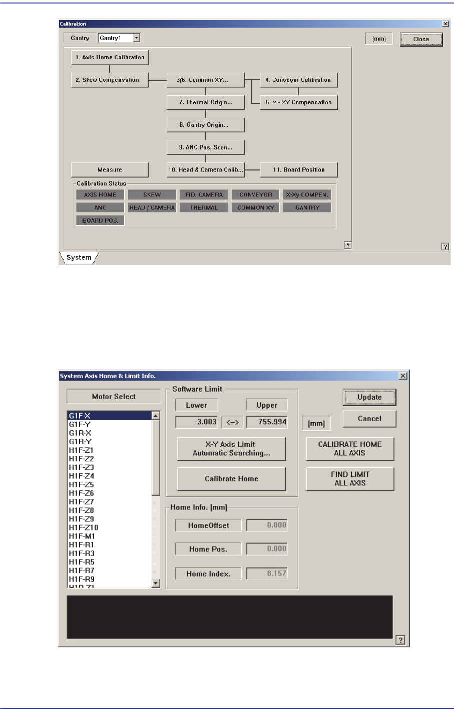
18.3.1. Axis Home Calibration
Sets the limit position of each axis to move. When this button is clicked on, the following
dialog box is displayed.
Figure18.7 “System Axis Limit Info.” dialog box
<Motor Select> list box
Select the motor axis for which to set the limit. Available axes are as follows.