DECAN_F2_Service(Eng_Ver1).pdf - 第80页
3-18 Fast & Flexible Chip Shooter DECAN F2 Service Manual 6) Push the PCB slowly and adjust the conveyor until when the PCB flows smoothly while passing the PCBs. 3.2. Commissioning 3.2.1. Checking Motor I/O 1) Check…
3-17
Installation & Operation
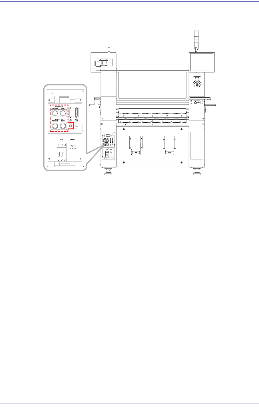
4) Set the communication interface between the printer and chip mounter by referring to
the following.
3.1.7. In-line Installation
The method to adjust level between the machines is as follows.
1) Move the component placer for which setup was already performed to a place near to
the conveyor and lower each foot to adjust the level roughly. At that position, adjust
the level of the machine at approximately 0.1mm/m level.
2) Move the machine by using a lever so that the gap between the conveyor and printer
conveyor that were already installed becomes 3~5mm.
3) Adjust the machine level again. (Refer to the previous leveling procedure)
4) Perform setup after placing the PCB on both the buffer conveyor and the conveyor for
the printing machine. Set the level difference between machines to 0.05~0.50mm
based on the ‘Down Flow’ in the direction in which the PCB flows so that the PCB
flows downward.
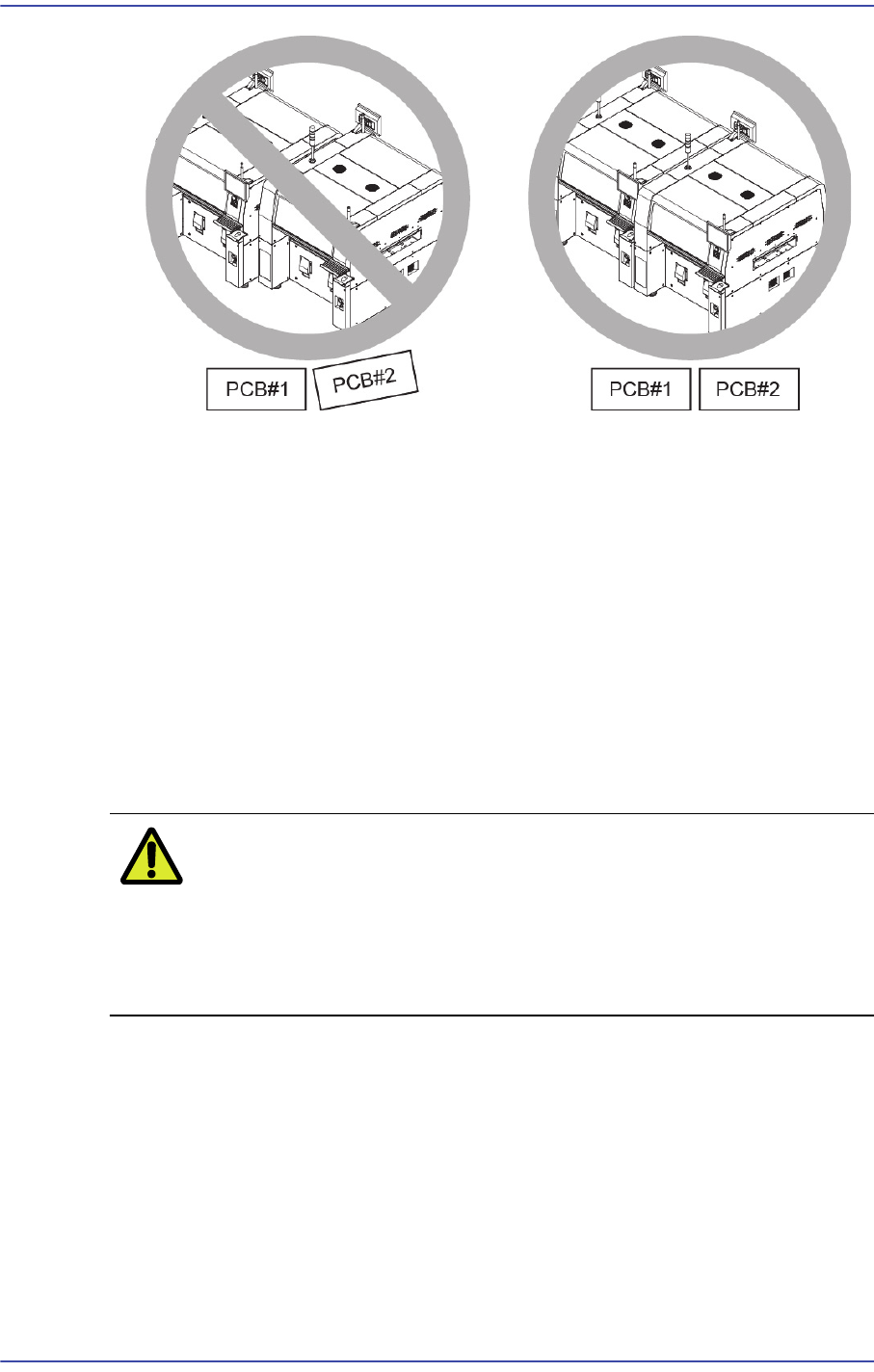
5) In order to adjust the straightness of PCB flow between machines, make each PCB
contact with the conveyor fixing frame and install the conveyor so that there will be no
gap between PCBs at the front and rear sides of the PCB.
3-18
Fast & Flexible Chip Shooter DECAN F2 Service Manual
6) Push the PCB slowly and adjust the conveyor until when the PCB flows smoothly
while passing the PCBs.
3.2. Commissioning
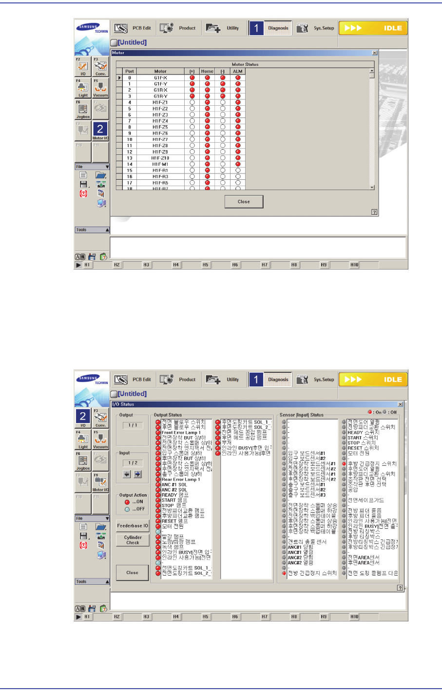
3.2.1. Checking Motor I/O
1) Checking Motor I/O1.Before turning on the main circuit breaker, check if there is any
element in the conveyor or inside the machine, which may cause problem.
2) If arrangement around the machine is finished, turn on the main switch to supply
power to the machine. At this time, check whether the front emergency switch is
released and then the front door is closed.
Caution If the power supply and internal of the machine are not
checked before turning on the main switch, the machine
may be damaged or personal injury may occur. Be sure to
check inside and outside of the machine before turning on
the main switch.
3) Once the MMI program is loaded, check the I/O of the XY motor with ‘Ready’ switch
on the front OP panel not pressed. Check if the +/- limit sensor and home sensor
operate normally for the XY motor by sensing the sensors manually. In this case, the
XY axis can be moved easily by hand.
3-19
Installation & Operation
3.2.2. Checking System I/O
1) Select the ‘Diagnosis’ menu in the menu and select submenu ‘I/O’
2) The <Output Status> group at the left of the ‘I/O Status’ dialog box indicates the
machine output.
3) Clicking the list in the <Sensor (Input) Status> group at the right of the ‘I/O Status’
dialog box will turn on/off the input of the corresponding machine and check the input
and output.