DECAN_F2_Service(Eng_Ver1).pdf - 第596页
18-76 Fast & Flexible Chip Shooter DECAN F2 Service Manual 1 1. .Select Gantry 2 in the <Gantry> comb o box and perform calibration in the same manner as has been d one for Gantry 1. The measurement result can …
18-75
Machine Calibration
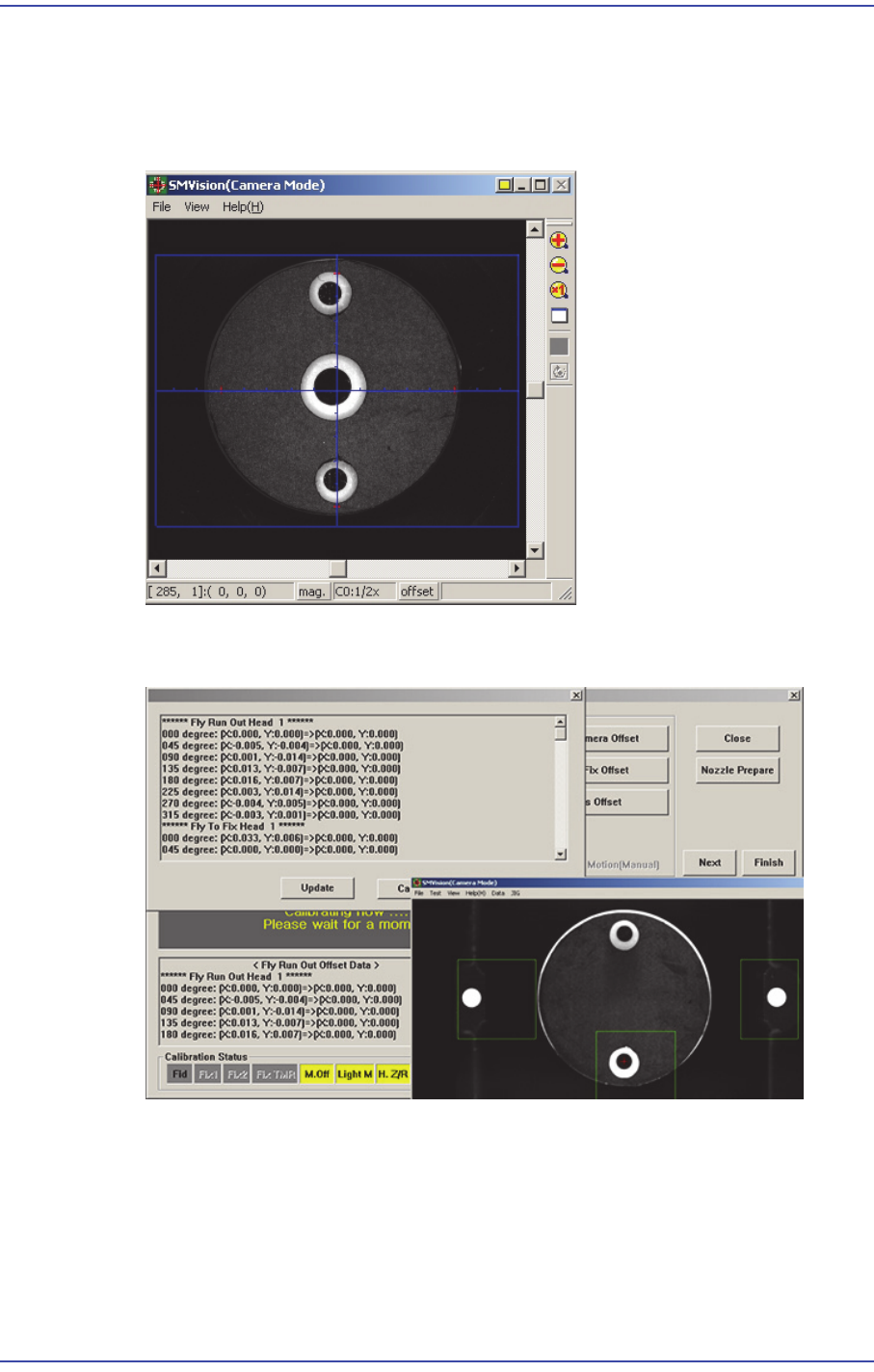
down at that spot. Then recognize the 2 fiducial marks on the upper surface of the
calibration tool by using the fiducial camera.
In this manner, rotate each head at 90 degree intervals and perform measurement in
four directions of 0, 90, 180 and 270 degrees.
9. If the calibration procedure is completed for all heads normally, the result is displayed
as shown in the following figure.
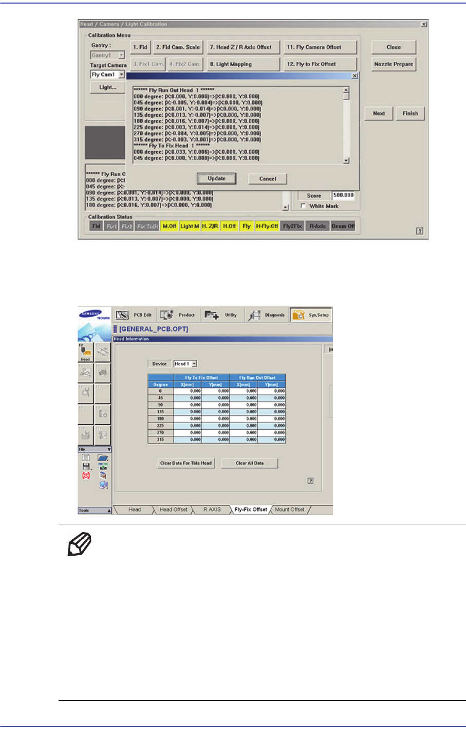
10. .From Head #2 to Head #10, perform calibration in the same manner as it was
performed for Head #1.If the calibration procedure is completed for all heads
normally, the result is displayed as shown in the following figure.
18-76
Fast & Flexible Chip Shooter DECAN F2 Service Manual
11. .Select Gantry 2 in the <Gantry> combo box and perform calibration in the same
manner as has been done for Gantry 1.
The measurement result can be confirmed in the Fly-Fix Offset dialog box
Memo The reference values for the calibration of the Fly to Fix Offset is as
follows.
Offset X : -0.050 ~ 0.050(mm)
Offset Y : -0.050 ~ 0.050(mm)
The reference values for the calibration of the Fly to Fix Offset is as
follows.
Offset X : -0.020 ~ 0.020(mm)
Offset Y : -0.020 ~ 0.020(mm)
18-77
Machine Calibration
18.3.10.8. R-Axis Offset Calibration
If the recognized angle and placement angle of the R axis are different, the R axis error
cannot be compensated through the Vision. Therefore, the placement accuracy decreases.
Therefore, perform R axis offset calibration to minimize such error by compensating an
approximate value with the R axis motion data.
The CN400 nozzle must be used to perform this calibration.
The following is the procedure to calibrate the ‘R-Axis Offset’:
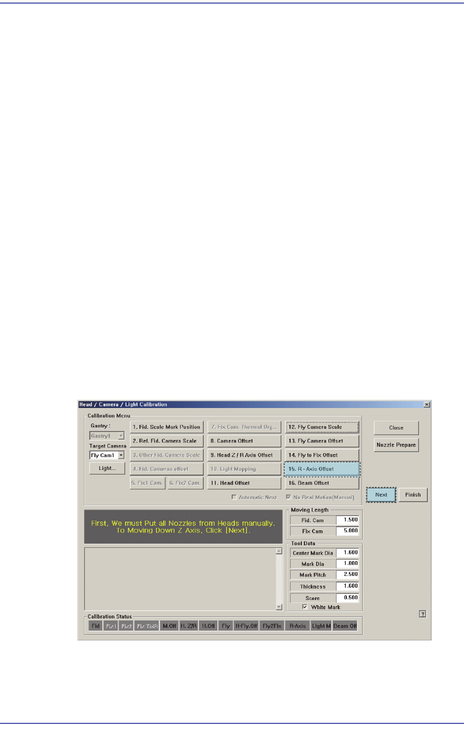
1. Click the <Nozzle Prepare> button and insert the CN400 nozzle into the No. 1 hole of
the ANC manually.
2. If the <15. R-Axis Offset> is clicked after selecting the <Automatic Next> check box,
calibration is performed for the selected gantry automatically.
If calibration is performed after selecting the <No Real Motion [Manual]> check box,
the nozzle is inserted into each head manually. Click the <Next> button to move onto
the next step.
If calibration is performed without selecting either the <Automatic> check box or
<Manual> check box, the nozzle is changed automatically for the currently selected
nozzle. Click the <Next> button to move onto the next step.
3. If the <15. R-Axis Offset> button is selected, the message “First, We must Put all
Nozzles From Heads on Manually. To Move down Z Axis, Click [Next]” appears.
Click the <Next> button to move down the Z axis of the head in order to manually
move all nozzles inserted in the nozzle-holder of the head.
4. Then, after the head assembly moves to the home position on the machine, move all Z
axes down. At this time, remove all inserted nozzles manually.
5. Then the message “Next Attach the Calibration Tool to Head 1. Click [Next] for