DECAN_F2_Service(Eng_Ver1).pdf - 第574页
18-54 Fast & Flexible Chip Shooter DECAN F2 Service Manual 8. Perform the calibration form Head 2 to Head 10 in the same manner . 9. Click the <Update> button to apply the calibration result to the machine.
18-53
Machine Calibration
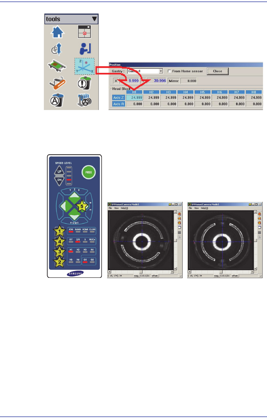
6. Rotate the spindle in the R-direction by using the teaching box so that the shape of the
nozzle holder becomes ‘( )’. At this time, the nozzle holders of the heads with
interlocked mechanism must be assembled in the same direction.
That is, the mechanisms of the #1~#2 heads and #3~#4 heads, #5~#6 heads, #7~#8
heads, #9~#10 heads must be assembled first in the same direction by using the jig for
a nozzle holder.
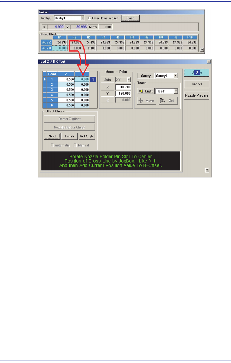
7. At this time, input the current position value of the R-axis and click the <Update>
button.
18-54
Fast & Flexible Chip Shooter DECAN F2 Service Manual
8. Perform the calibration form Head 2 to Head 10 in the same manner.
9. Click the <Update> button to apply the calibration result to the machine.
18-55
Machine Calibration
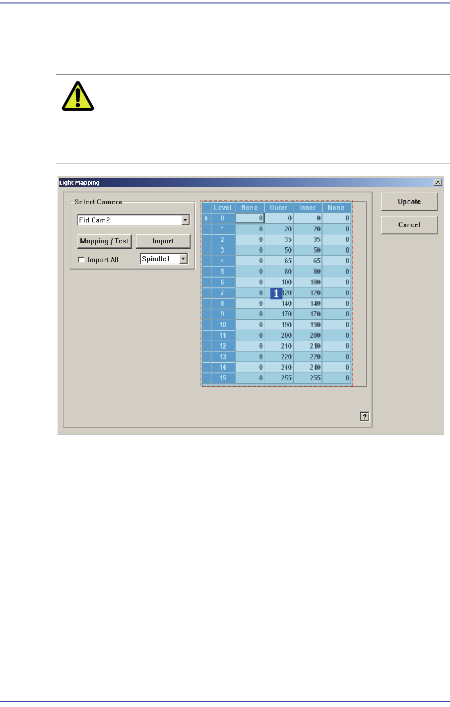
18.3.10.3. Light Mapping
Calibrate the brightness of the light for the camera. In order to perform this calibration,
insert the LightFix into the No. 1 nozzle of the ANC.
Caution Since the nozzle for the SM32x,SM411, SM421 model is
not compatible to the one for the light mapping used for the
SM32x,SM411, SM421 model, do not use it for this
machine.
1: Light Level group
<Select Camera> combo box
Selection Control
Select the camera to perform light mapping.
Light Level group
Sets the brightness by light level.
<Level> column
Dislays 16 steps of lighting.
<Side>/ <Outer>/ <Coaxial> column
For the Fly Camera: Input the side illumination value within the range of 256
values.
For the Fix Camera: Input the side illumination value within the range of 4096