DECAN_F2_Service(Eng_Ver1).pdf - 第546页
18-26 Fast & Flexible Chip Shooter DECAN F2 Service Manual 2. Adjust the position of the fi ducial camera by using the te aching box so that the center of the cross hair displayed in the SMV ision window matches with…
18-25
Machine Calibration
Select the Fiducial camera to be moved.
<Move> button
Move the fiducial camera of the selected gantry.
Warning Operation error caused by unauthorized or untrained
personnel or insufficient checking before calibration could
severely damage the machine
or the set up data, or it could cause personal injury of the
operator or the worker near the machine.
Before carrying out calibration, check the item to be
calibrated and check if there is any worker near the
machine.
And calibration must be carried out by an authorized and
trained user only.
<Light> button
Inner
Adjusts the inner lighting for the Down Camera of the selected Gantry.
Outer
Adjusts the outer lighting for the Down Camera of the selected Gantry.
18.3.4.1. Procedure
The automatic setup method is as follows.
1. Click the <Move> button to move the fiducial camera to the designated position.
2. Adjust the position of the fiducial camera by using the teaching box so that the center
of the cross hair displayed in the SMVision window matches with the center of the
fiducial mark that was already set on the conveyor. At this time, all gantry cameras
have to be movable to this position.
3. Click the <Get> button to reflect the current coordinate.
4. If the <Next> button is clicked after selecting the <Automatic Next> check box, the
same movement is performed automatically.
5. If finished properly, click the <Update> button.
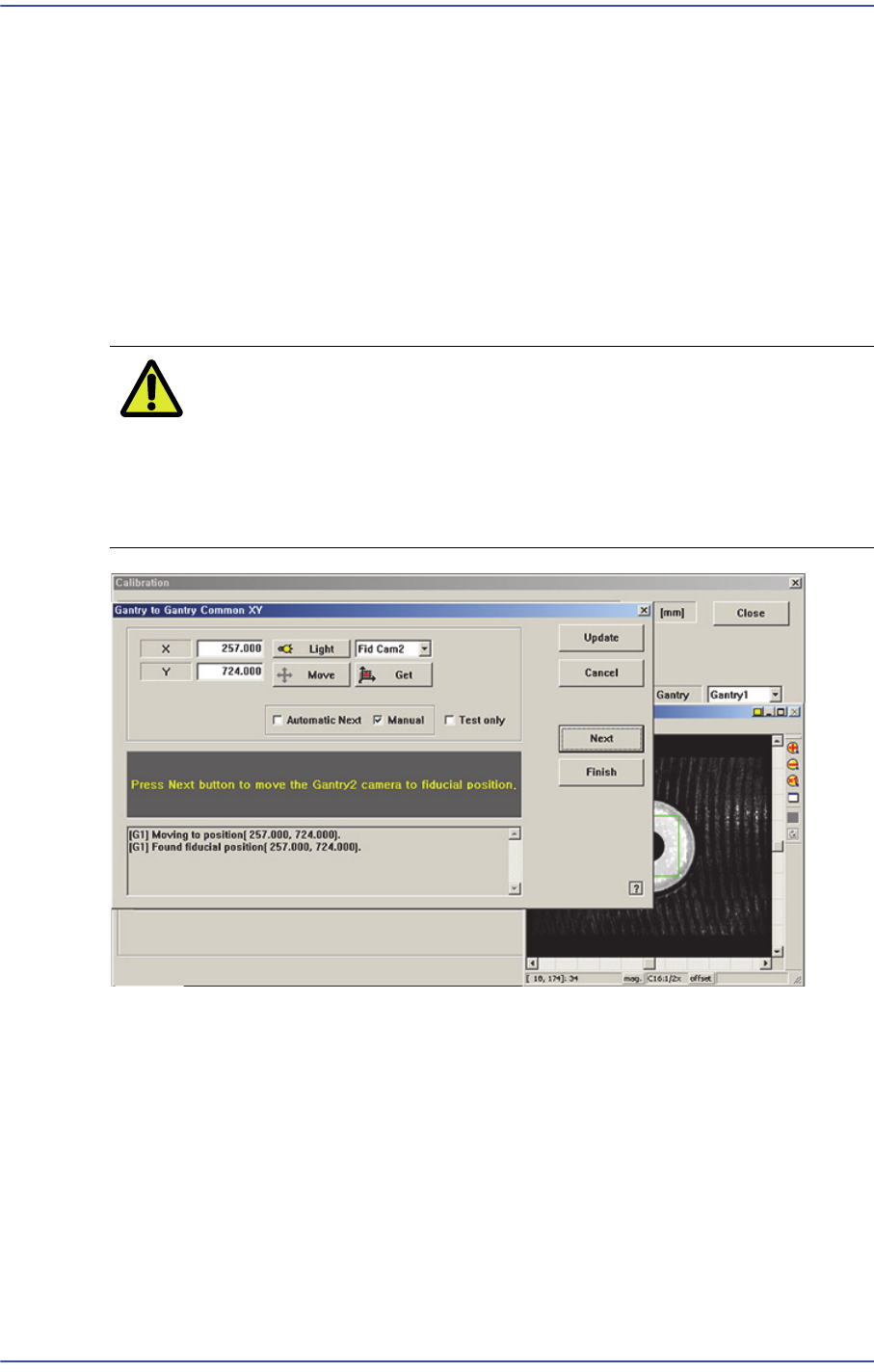
The manual setup method is as follows.
1. Move the fiducial camera of the corresponding gantry to the position of the fiducial
mark selected from the Grid group.
18-26
Fast & Flexible Chip Shooter DECAN F2 Service Manual
2. Adjust the position of the fiducial camera by using the teaching box so that the center
of the cross hair displayed in the SMVision window matches with the center of the
fiducial mark that was already set on the conveyor. At this time, all gantry cameras
have to be movable to this position.
3. Click <Get> button to reflect the current coordinate.
4. move the other gantries to the position designated in step 1.
5. Click <Get> button to reflect the current coordinate.
6. Wait until the Gantry moves to Home, automatically detects Collision sensor, and
returns to Home again.
Caution Be sure to perform the “Gantry to Gantry Common XY”
calibration before performing the ‘Gantry Mapping’ (Disable
Condition). If ‘Gantry Mapping’ is already enabled, perform
the ‘Gantry to Gantry Common XY” calibration after
disabling the ‘Gantry Mapping’.
18-27
Machine Calibration
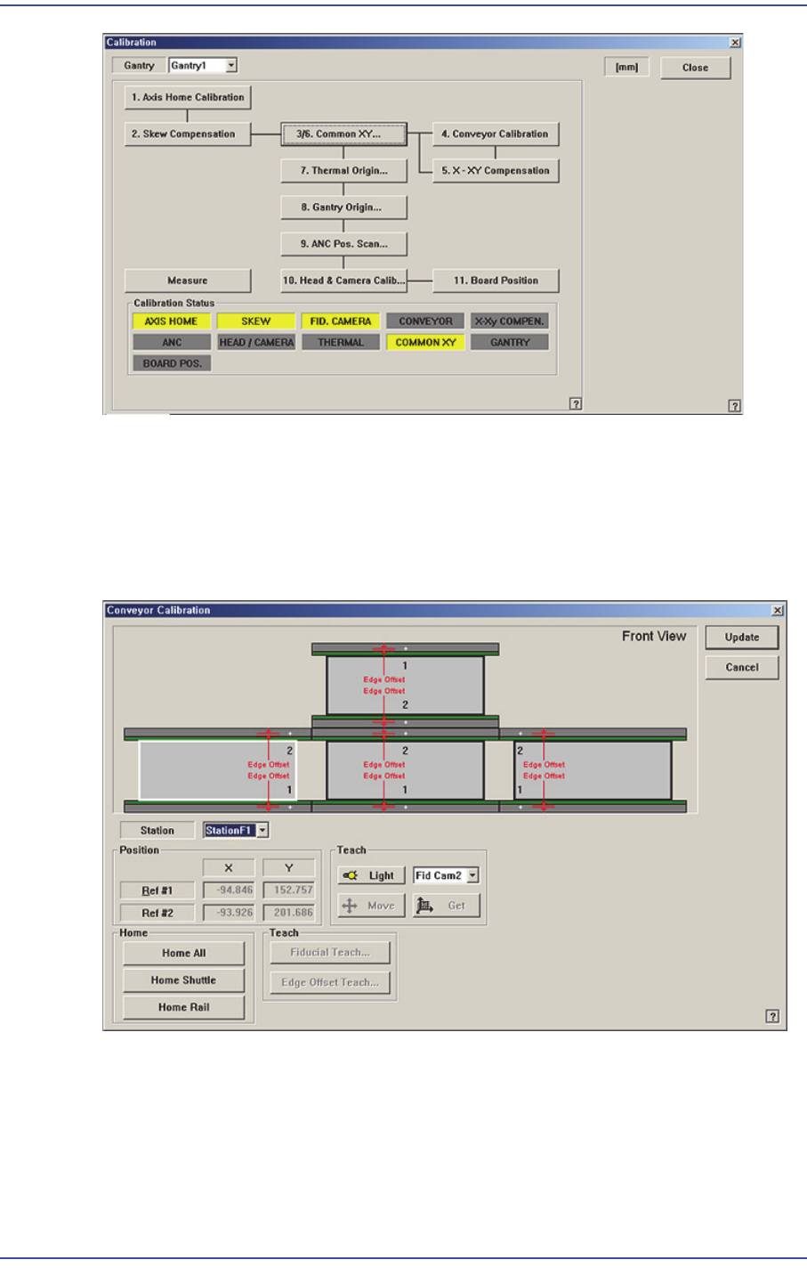
18.3.5. Conveyor Calibration
Calibration is made upon initial installation of the machine. The recalibration of transport
rail should be performed when mechanical adjustments to the transport rail occur.
Figure18.9 "Conveyor Calibration" dialog box
<Station> combo box
Select the Station.
<Position> group
Input the position of the fiducial mark of the selected station. First click the <Home
All> button to enable this edit box and find the home position for all axes related to the
conveyor.