DECAN_F2_Service(Eng_Ver1).pdf - 第116页
5-16 Fast & Flexible Chip Shooter DECAN F2 Service Manual Ref The part number of the new Outer PCB A is AM03-005095A. The part number of the new Outer PCB B is AM03-005 097A. 7) Assemble the board in the reverse orde…
5-15
Head
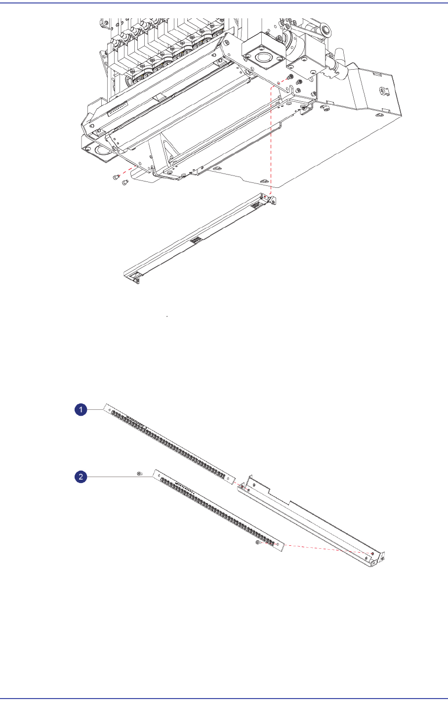
5) Unscrew the fixing bolts(4-M2.5*4) securing Outer B PCB and remove it.
1: Outer PCB A
2: Outer PCB B
6) Replace the Outer PCB with a new one.
5-16
Fast & Flexible Chip Shooter DECAN F2 Service Manual
Ref The part number of the new Outer PCB A is AM03-005095A.
The part number of the new Outer PCB B is AM03-005097A.
7) Assemble the board in the reverse order of disassembling.
8) Once the assembling is completed, turn on the main switch on the front of the machine
and boot the PC.
9) Perform the following calibrations.
Light Mapping
Total Time : 0.5Hour
5.4.4. Coaxial Illumination Replacement Procedure
1) Manipulate the teaching box to move the head module to the front.
2) Close the PC as usual and turn off the main switch at the front of the machine.
3) Remove the connectors connected to the Coaxial PCB.
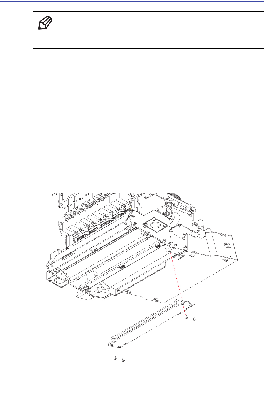
4) Unscrew the fixing bolts(4-M2.5*4) securing the Coaxial Assy and remove it.
5) Unscrew the fixing bolts(4-M2*4) securing Coaxial PCB and remove it.
5-17
Head
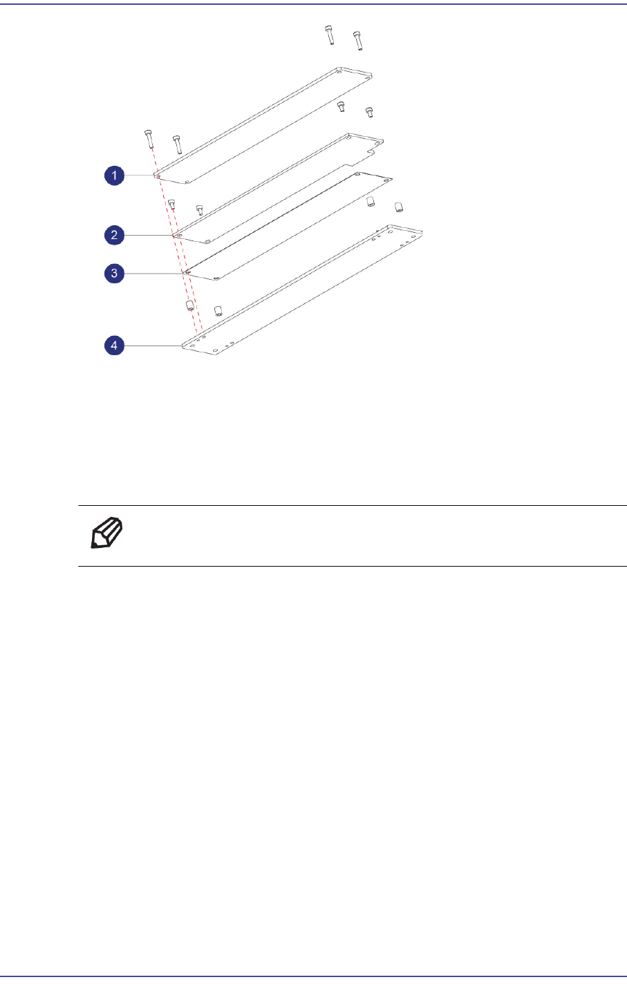
1: DIFFUSEER
2: Coaxial PCB
3: Insulation
4: Plate
6) Replace the PCB with a new one.
Ref The part number of the new PCB A is AM03-005100A.
7) Assemble the board in the reverse order of disassembling.
8) Once the assembling is completed, turn on the main switch on the front of the machine
and boot the PC.
9) Perform the following calibrations.
Light Mapping
Total Time : 0.5Hour
5.4.5. Side Illumination Replacement Procedure
1) Manipulate the teaching box to move the head module to the front.
2) Close the PC as usual and turn off the main switch at the front of the machine.
3) Remove the connectors connected to the Side PCB.
4) Unscrew the fixing bolts(4-M3*8) securing the Side Assy and remove it.