DECAN_F2_Service(Eng_Ver1).pdf - 第578页
18-58 Fast & Flexible Chip Shooter DECAN F2 Service Manual CIRCLE: Refers to the round area. RECT : Refers to the rectangular area. NONE: Area not designated <2. Camera> group Selects the camera for performin…
18-57
Machine Calibration
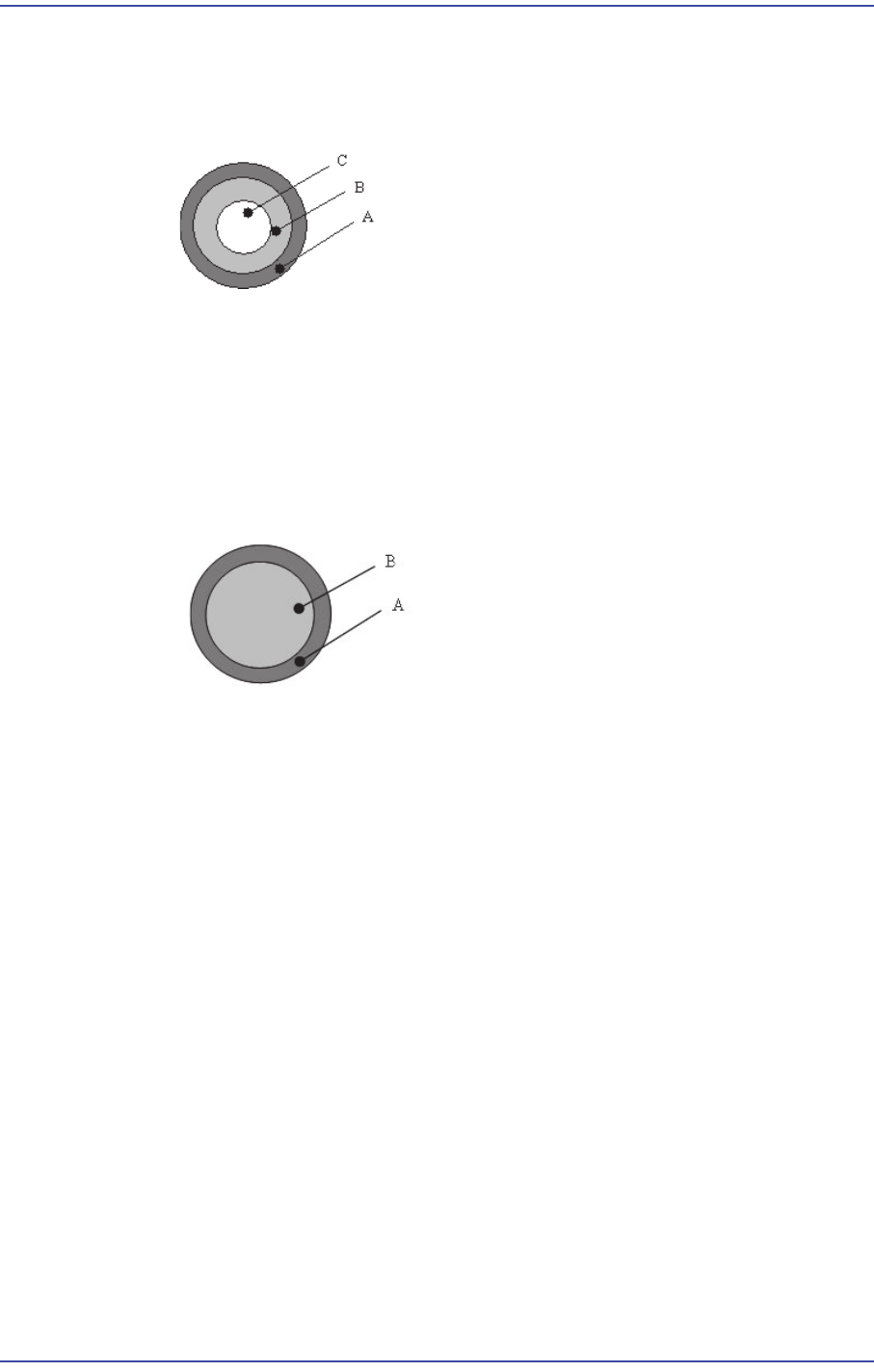
designated together. That is, the area is designated in the form of circle band.
There are a total of 4 areas, among which Area 1 ~ Area 4 are corresponding areas.
Do not change the value since it is set automatically.
[Bottom Shape of Calibration Nozzle for Small-Fix Camera]
Test Area1 =Search Area(A) –Excluded Area (B +C)
Test Area2 =Search Area(B) –Excluded Area (C)
Test Area3 =Search Area(C)
Test Area4 =Test Area1 +Test Area2 +Test Area3
There are a total of 3 areas, among which Area 1 ~ Area 3 are corresponding areas.
[Bottom shape of the calibration nozzle for the fid camera]
Test Area1 =Search Area(A) –Excluded Area (B)
Test Area2 =Search Area(B)
Test Area3 =Test Area1 +Test Area2
<No> column
Displays the serial number of the test are.
<Pos X> column
Displays the X coordinate of the area center.
<Pos Y> column
Displays the Y coordinate of the area center.
<Size X> column
Displays the area size in the X direction.
<Size Y> column
Displays the area size in the Y direction.
<Type> column
Designates the shape of the area.
18-58
Fast & Flexible Chip Shooter DECAN F2 Service Manual
CIRCLE: Refers to the round area.
RECT: Refers to the rectangular area.
NONE: Area not designated
<2. Camera> group
Selects the camera for performing lighting brightness test or mapping. Activated
cameras can be designated at the same time.
<3. Tool Setting> group
Performs test or preparation for mapping.
<Prepare Test /Mapping> button
Return all nozzles mounted on the head to each corresponding ANC hole.
Before doing so, arrange the LightFly nozzle, a nozzle for calibration into the
No. 1 hole of the ANC.
If the nozzle arrangement is finished, the <Start> button and <Test> button in
the <Mapping>group.
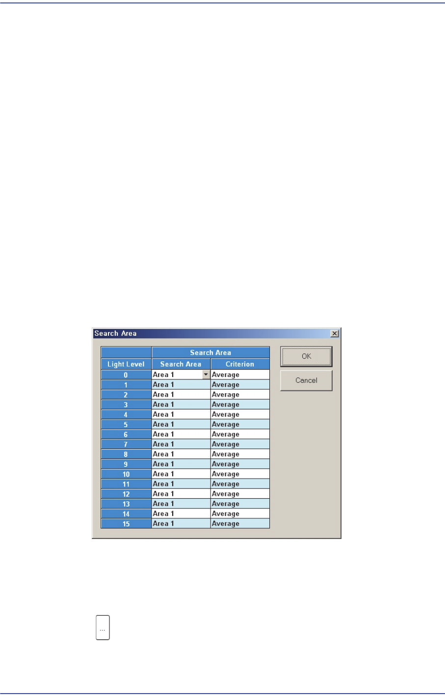
<4. Search Area> group
Clicking the button corresponding to the light for which mapping is to be
performed will display the following dialog box.
Click on the button corresponding to the illumination for mapping, set the test area
(Area 1 ~ 4) to 16 illumination levels for each lighting, and setup the average
illumination level for each pixel of the test area to the maximum value.
<Mapping> group
button
Select the Map File to be used for mapping. Since the file name is set
automatically, do not change it.

18-59
Machine Calibration
<Start> button
Start the Mapping.
<Test> button
Perform test for the mapping result. The light level that does not satisfy the
reference value is searched automatically and it is displayed in the result file.
Perform mapping with the <Refine Mapping Result> check box being selected.
State display
Displays current progressing state.
Camera (Number of camera for which test or maping is completed) /(Total number
of selected camera)
(I: Inner Level, O: Outer Level, S: Side Level, B: Back Level)
<Close> button
Closes the dialog box.
<Update> button
Transmits the set data to the equipment and closes the dialog box.
<Cancel> button
Ignores the set data and closes the dialog box.