00195981-03_SM_SWS_DE.pdf - 第21页
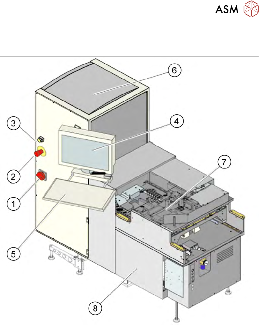
2 Übersicht über das SIPLACE Wafer System (SWS) Serviceanleitung SIPLACE Wafer System (SWS) 11/2018 21 2 Übersicht über das SIPLACE Wafer System (SWS) Abb.2: SIPLACE Wafer System (SWS) - Gesamtansicht 1 Hauptschalter …

1 Einleitung
1.5 Abkürzungen
20 Serviceanleitung SIPLACE Wafer System (SWS) 11/2018
2 Übersicht über das SIPLACE Wafer System (SWS)
Serviceanleitung SIPLACE Wafer System (SWS) 11/2018 21
2 Übersicht über das SIPLACE Wafer System
(SWS)
Abb.2: SIPLACE Wafer System (SWS) - Gesamtansicht
1 Hauptschalter 2 Not-Halt-Taster
3 Meldeleuchte 4 Bildschirm
5 Tastatur 6 Wafer-Wechsel-System
7 Grundaufbau 8 Versorgungseinheit
2 Übersicht über das SIPLACE Wafer System (SWS)
2.1 Technische Daten
22 Serviceanleitung SIPLACE Wafer System (SWS) 11/2018
2.1 Technische Daten
SIPLACE Wafer-System
Bestückverfahren Flip-Chip, Die-Attach
Die-Größe 0,8 mm x 0,8mm bis zu bis 12 x12 mm (größere Dies auf Anfrage)
Die-Dicke 0,05 mm bis 4 mm
Wafer-Größe bis zu 12"
Frame-Größe bis zu 15"
Wafer-Kassette max. 25 Slots
2.2 Übersicht der Hauptbaugruppen
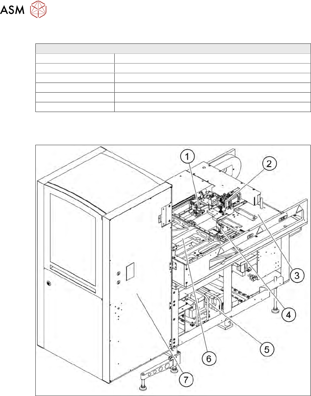
Das SWS besteht aus den folgenden Hauptbaugruppen:
Abb.3: Übersicht SWS - Vorderseite
1. Greifer
2. Flip-Unit
3. Einbauplatz für Optionen (Die-Attach-Unit) oder Linear-Dipping-Unit
4. Die-Ejector
5. Versorgungseinheit
6. X/Y-Unit