00195982-03_SM_SWS_EN.pdf - 第108页
6 Supply unit 6.1 Overview of spare parts 108 Service Manual SIPLACE Wafer System (SWS) 11/2018 Fig.114: Electrical unit from the front - detailed view Fig.115: Supply unit from the back
6 Supply unit
6.1 Overview of spare parts
Service Manual SIPLACE Wafer System (SWS) 11/2018 107
6 Supply unit
According to the location there are two different variants that only differ in their mirrored arrange-
ment of the modules.
●
Supply unit SWS12 (1,3) - [03096039-xx]
●
Supply unit SWS12 (2,4) - [03096139-xx]
The supply unit is located in the bottom part of the SWS. This also houses the supply unit and the
main electrical components.
NOTICE
Observe the circuit diagrams.
Details of the electrical assemblies in the supply unit can be found in the circuit diagrams
[00195960‑xx].
6.1 Overview of spare parts
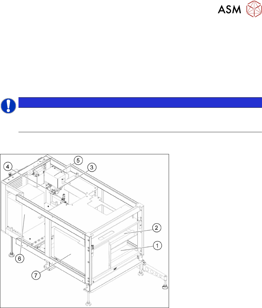
Fig.113: Supply unit from the front
6 Supply unit
6.1 Overview of spare parts
108 Service Manual SIPLACE Wafer System (SWS) 11/2018
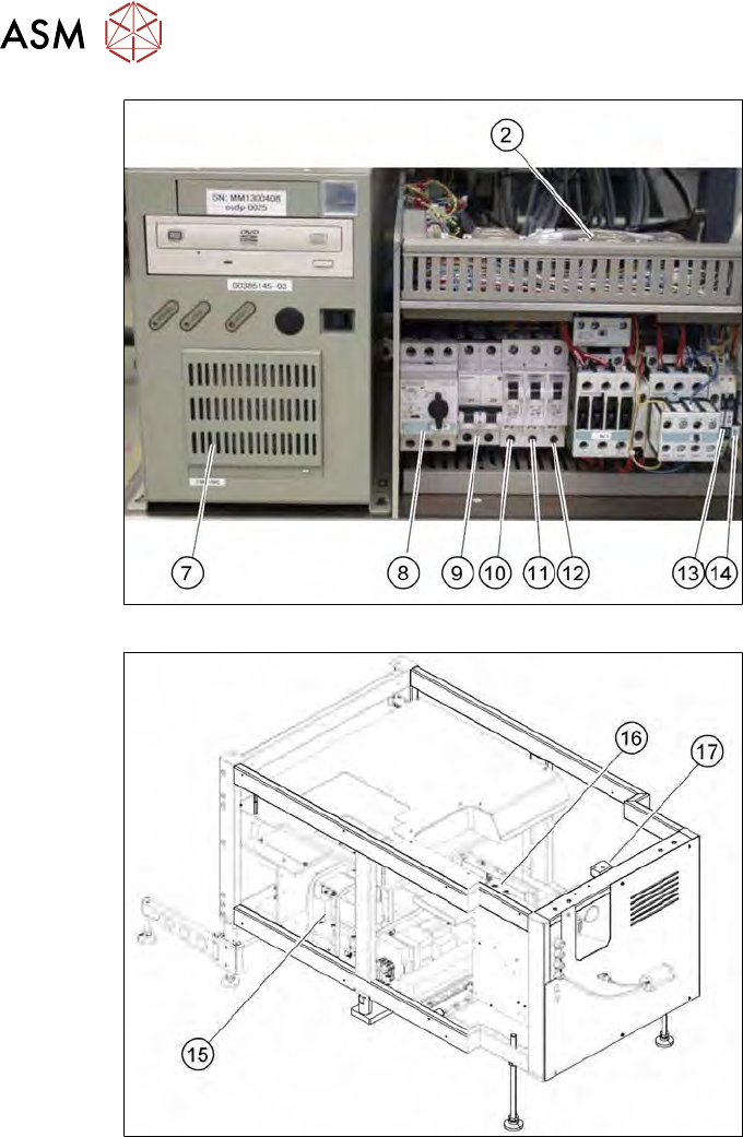
Fig.114: Electrical unit from the front - detailed view
Fig.115: Supply unit from the back
6 Supply unit
6.1 Overview of spare parts
Service Manual SIPLACE Wafer System (SWS) 11/2018 109
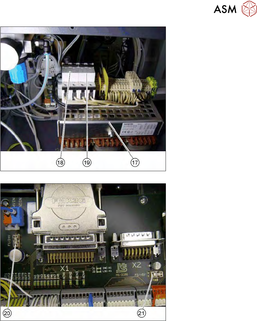
Fig.116: Fuses on the mains transformer
Fig.117: Fuses on the board with placement DMC-INT2 Rev.0