00195982-03_SM_SWS_EN.pdf - 第23页
2 Overview of the SIPLACE wafer system (SWS) 2.2 Overview of main assemblies Service Manual SIPLACE Wafer System (SWS) 11/2018 23 View of SWS from behind (machine end) Fig.4: Overview of SWS – back 1. Basic frame 2. Bar…
2 Overview of the SIPLACE wafer system (SWS)
2.2 Overview of main assemblies
22 Service Manual SIPLACE Wafer System (SWS) 11/2018
2.2 Overview of main assemblies
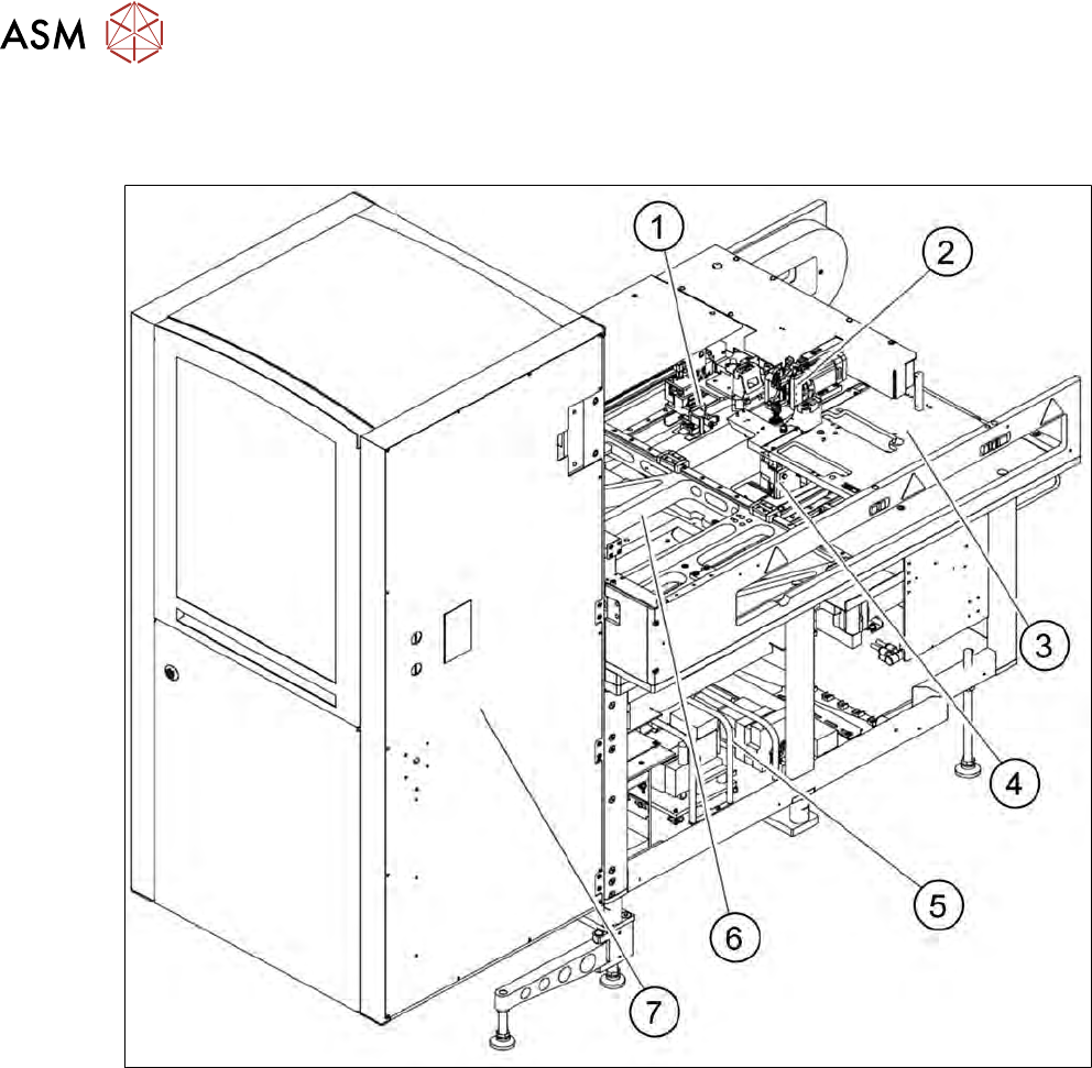
The SWS consists of the following main assemblies:
Fig.3: Overview of SWS - front
1. Gripper
2. Flip unit
3. Installation location for options (die attach unit) or linear dipping unit
4. Die ejector
5. Supply unit
6. X/Y unit
7. Magazine lift
2 Overview of the SIPLACE wafer system (SWS)
2.2 Overview of main assemblies
Service Manual SIPLACE Wafer System (SWS) 11/2018 23
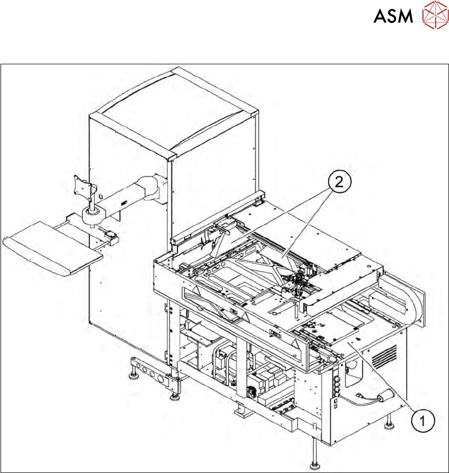
View of SWS from behind (machine end)
Fig.4: Overview of SWS – back
1. Basic frame
2. Barcode scanner on the wafer magazine lift or next to the gripper unit (depending on configur-
ation)
2 Overview of the SIPLACE wafer system (SWS)
2.2 Overview of main assemblies
24 Service Manual SIPLACE Wafer System (SWS) 11/2018
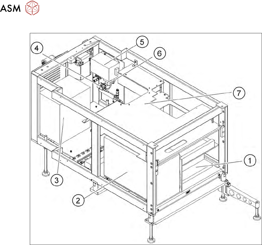
View of SWS from the front (magazine lift removed)
Fig.5: SWS supply unit, view from the front
1. Electrical unit, view from the front
2. Computer unit
3. Transformer
4. Push switch
5. Main power filter
6. Solenoid valve
7. Cover