00195982-03_SM_SWS_EN.pdf - 第96页
5 Basic frame – X/Y unit 5.3 Replacing parts 96 Service Manual SIPLACE Wafer System (SWS) 11/2018 Fig.95: ► Fasten the four screws for the spindle plate onto the coupling plate. Secure the screws with Loctite 243. ► Now…
5 Basic frame – X/Y unit
5.3 Replacing parts
Service Manual SIPLACE Wafer System (SWS) 11/2018 95
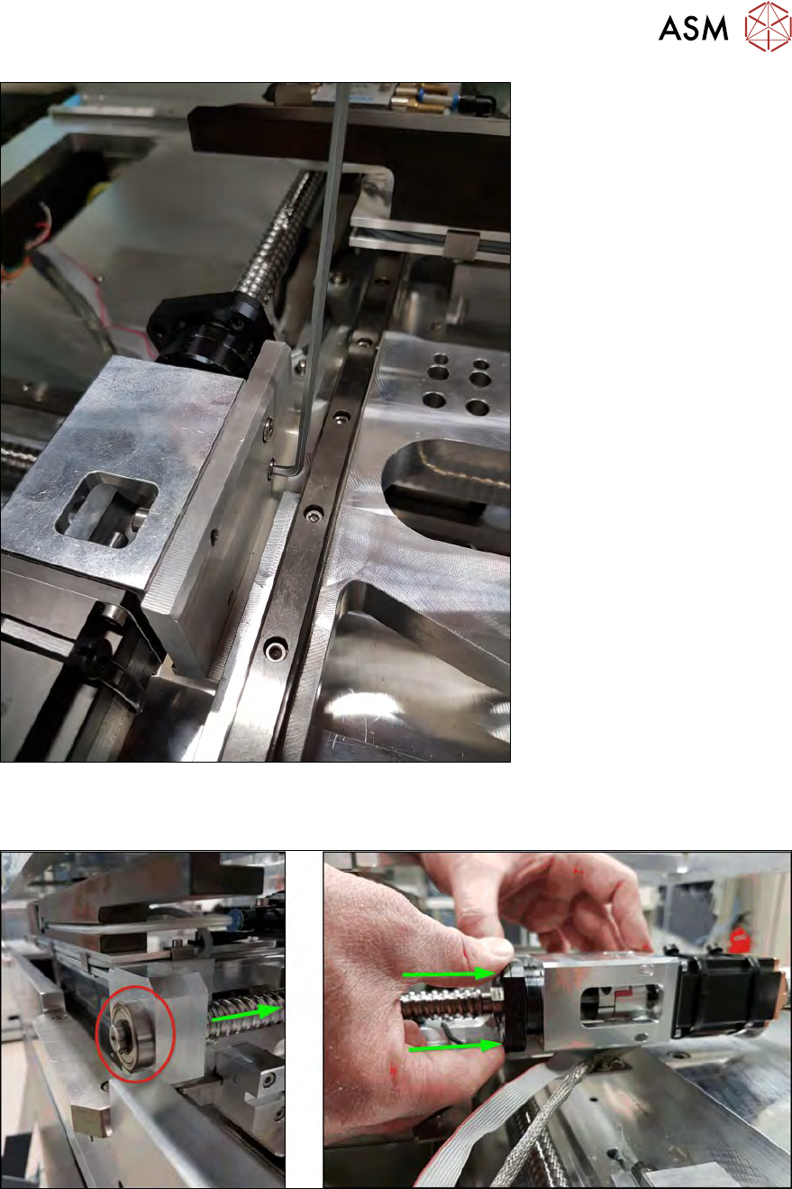
Fig.93:
► Now slightly tighten the two fastening screws on the rear (with shortened, modified Allen key).
Secure the screws with Loctite 243.
Fig.94:
► Now carefully press the spindle plate and the whole spindle into the coupling plate.
Make sure that the spindle bearing moves smoothly and easily into the bearing shell.
5 Basic frame – X/Y unit
5.3 Replacing parts
96 Service Manual SIPLACE Wafer System (SWS) 11/2018
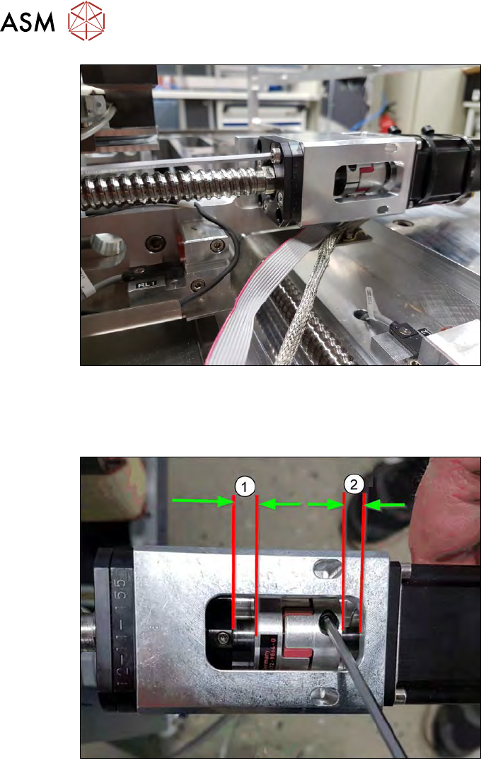
Fig.95:
► Fasten the four screws for the spindle plate onto the coupling plate.
Secure the screws with Loctite 243.
► Now screw the coupling plate into place.
Fig.96:
► Align the coupling.
(1) approx. 6mm
(2) approx. 4mm
► Tighten the two clamping screws on the coupling!
5 Basic frame – X/Y unit
5.3 Replacing parts
Service Manual SIPLACE Wafer System (SWS) 11/2018 97
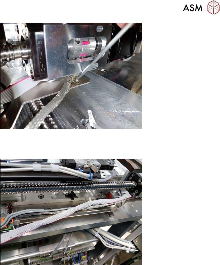
Fig.97:
► Lift the cable downholder over the shielded cable and carefully tighten the screw with the ball
head of the Allen key.
The cable should be aligned parallel to the X axis.
Fig.98:
► As shown in the diagram above, run the cable without twisting!