00195982-03_SM_SWS_EN.pdf - 第21页
2 Overview of the SIPLACE wafer system (SWS) 2.1 Technical data Service Manual SIPLACE Wafer System (SWS) 11/2018 21 2 Overview of the SIPLACE wafer system (SWS) Fig.2: SIPLACE wafer system (SWS) - overview 1 Main switc…

1 Introduction
1.5 Abbreviations
20 Service Manual SIPLACE Wafer System (SWS) 11/2018
2 Overview of the SIPLACE wafer system (SWS)
2.1 Technical data
Service Manual SIPLACE Wafer System (SWS) 11/2018 21
2 Overview of the SIPLACE wafer system (SWS)
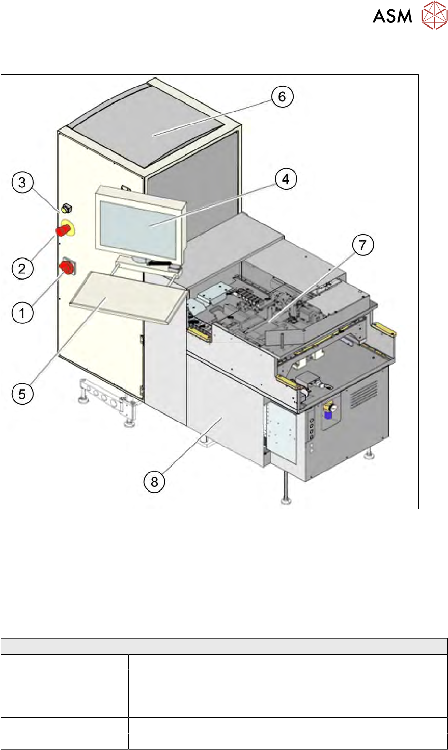
Fig.2: SIPLACE wafer system (SWS) - overview
1 Main switch 2 EMERGENCY OFF button
3 Indicator lamp 4 Monitor
5 Keyboard 6 Wafer change system
7 Basic design 8 Supply unit
2.1 Technical data
SIPLACE wafer system
Placement process Flip chip, die attach
Die size 0.8 mm x 0.8mm up to 12 x 12 mm (larger dies on request)
Die thickness 0.05 mm to 4mm
Wafer size Up to 12"
Frame size Up to 15"
Wafer cassette Max. 25 slots
2 Overview of the SIPLACE wafer system (SWS)
2.2 Overview of main assemblies
22 Service Manual SIPLACE Wafer System (SWS) 11/2018
2.2 Overview of main assemblies
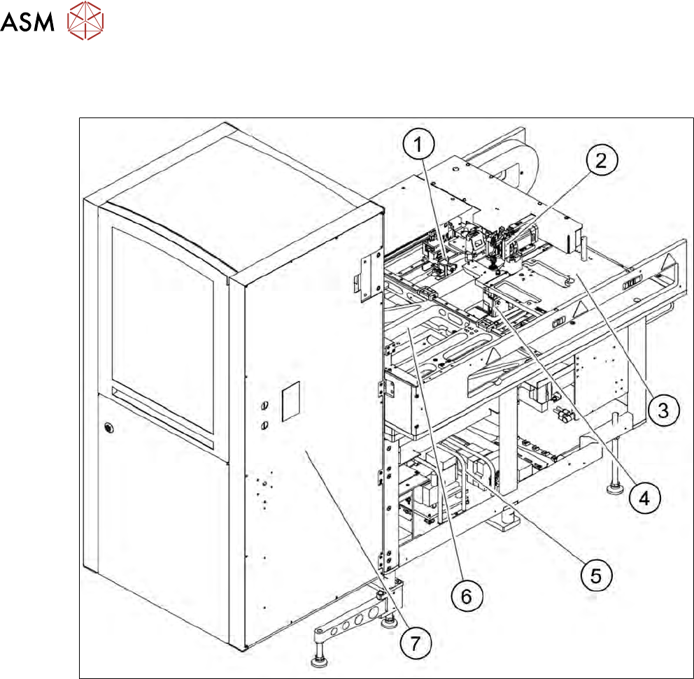
The SWS consists of the following main assemblies:
Fig.3: Overview of SWS - front
1. Gripper
2. Flip unit
3. Installation location for options (die attach unit) or linear dipping unit
4. Die ejector
5. Supply unit
6. X/Y unit
7. Magazine lift