00195982-03_SM_SWS_EN.pdf - 第161页
7 Die ejector 7.5 Mechanical adjustment of the die ejector unit in the Z direction (focus) Service Manual SIPLACE Wafer System (SWS) 11/2018 161 Fig.206: ► Check the black cap. This must be seated fully on the base unit…
7 Die ejector
7.5 Mechanical adjustment of the die ejector unit in the Z direction (focus)
160 Service Manual SIPLACE Wafer System (SWS) 11/2018
7.5.1.4 Checking the needle ejection unit for air-tightness
► In the toolbar, select the button Service Settings => Main vacuum control system (see
14.1 "SWS GUI - service settings" [}357]).
► The Main vacuum should be between 740 and 840 mbar.
► Place a piece of foil onto the ejection system, so that all openings are closed.
► Now switch on the vacuum at the die ejector.
► Enable Vacuum valve ejection unit opened.
ð Suction will be applied to the foil by the ejection system.
ð The Main vacuum should reach the value previously shown, if possible (i.e. no losses).
Troubleshooting in the event of leakages
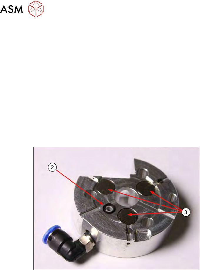
► Switch the vacuum on at the die ejector (software) and check the suction force at the sealing
lip with your finger(2).
► Check whether the vacuum inlet cable is free of bends/folds.
Fig.205:
► Perform a sight check of the sealing lip (2) for possible damage and replace, if necessary (see
7.5.1.5 "Replacing the sealing unit and the O-ring on the die ejector centering unit" [}162]).
► Check the magnets (3) for foreign bodies.
7 Die ejector
7.5 Mechanical adjustment of the die ejector unit in the Z direction (focus)
Service Manual SIPLACE Wafer System (SWS) 11/2018 161
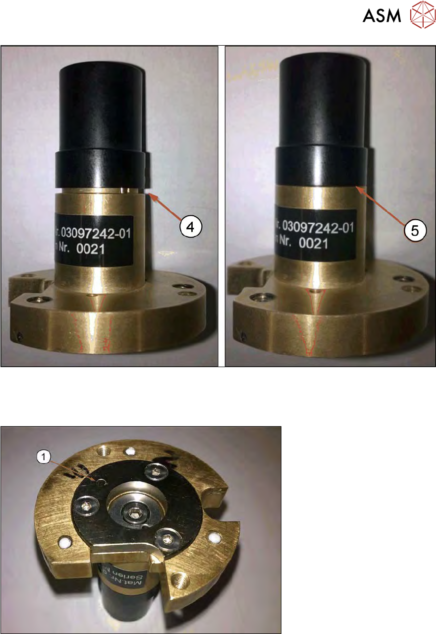
Fig.206:
► Check the black cap. This must be seated fully on the base unit of the ejection system.
(4) Gap → vacuum leakage → bad
(5) No gap → good
Fig.207:
► Check the polished sealing surface and the ejection system vacuum hole(1) for damage or
dirt.
7 Die ejector
7.5 Mechanical adjustment of the die ejector unit in the Z direction (focus)
162 Service Manual SIPLACE Wafer System (SWS) 11/2018
7.5.1.5 Replacing the sealing unit and the O-ring on the die ejector centering unit
The following description is explained using the new needle ejector unit (magnetic). The procedure
is identical for the needle ejector unit with the bayonet fastening.
Parts
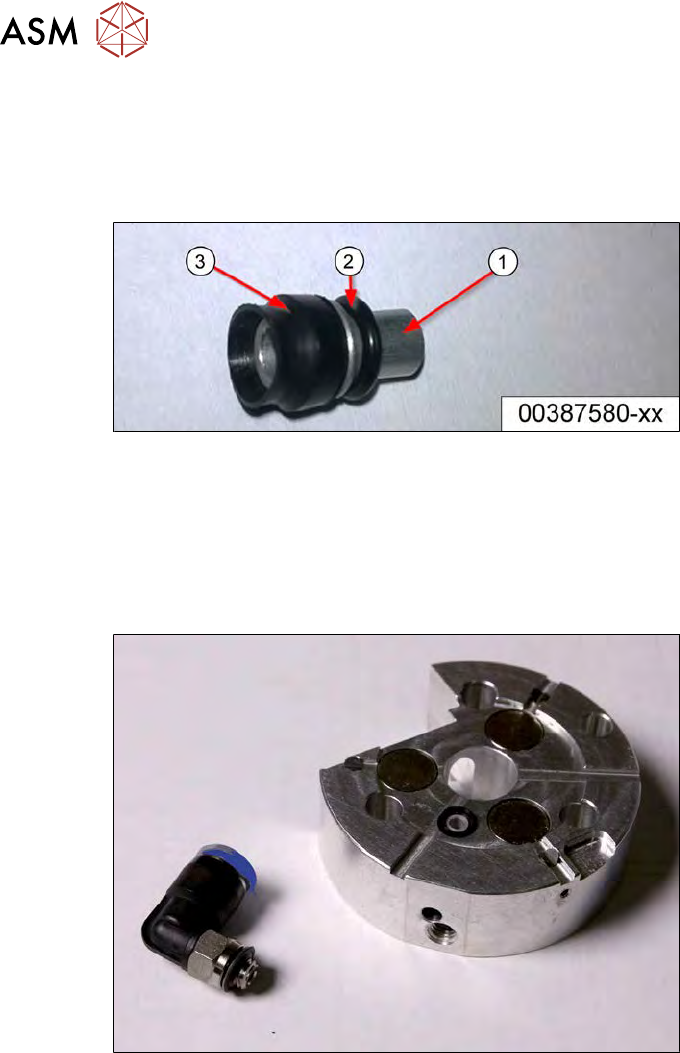
Fig.208:
The following spare parts are available:
●
[00387580-xx] Sealing unit
(suction adapter (1) incl. vacuum suction unit (2) and O-ring (3) prefitted)
●
[00201141-xx] O-ring 3*1 NBR 70 B (defined as maintenance/wear part)
Procedure
Fig.209:
► Remove the pneumatic connection using a fork wrench. Pay attention to the seals.