00195982-03_SM_SWS_EN.pdf - 第77页
5 Basic frame – X/Y unit 5.3 Replacing parts Service Manual SIPLACE Wafer System (SWS) 11/2018 77 Fig.59: ► Remove the coupling clamping screw for the motor shaft. You might need to widen the coupling clamp with a screw…
5 Basic frame – X/Y unit
5.3 Replacing parts
76 Service Manual SIPLACE Wafer System (SWS) 11/2018
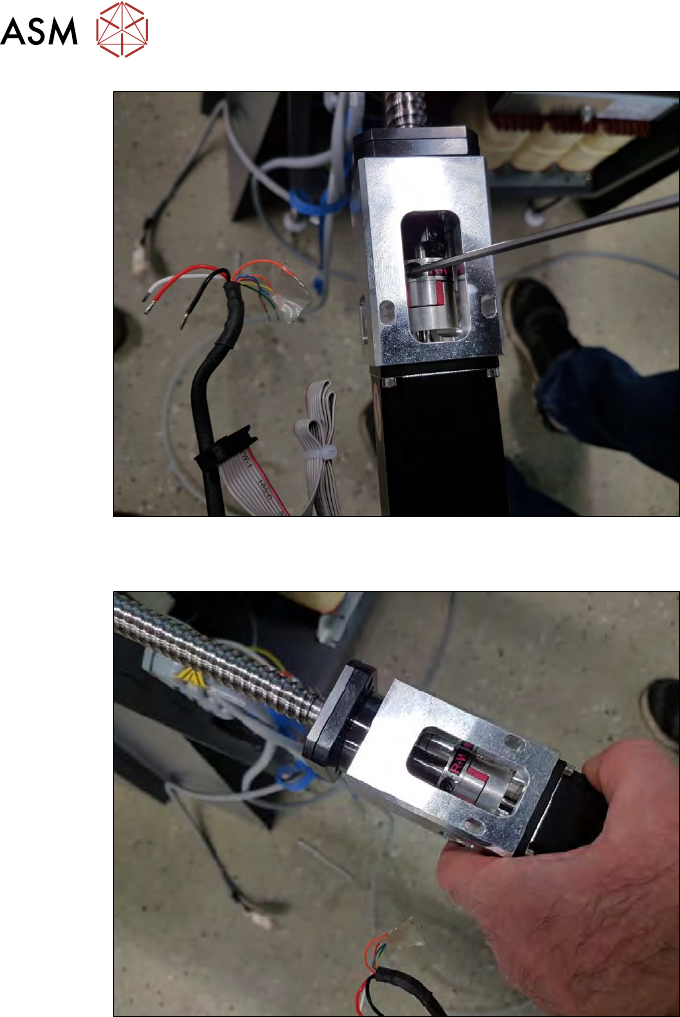
Fig.57:
► Remove the clamping screw for the coupling shown in the diagram!
Fig.58:
► Carefully pull the whole coupling plate-motor-coupling unit off the spindle.
5 Basic frame – X/Y unit
5.3 Replacing parts
Service Manual SIPLACE Wafer System (SWS) 11/2018 77
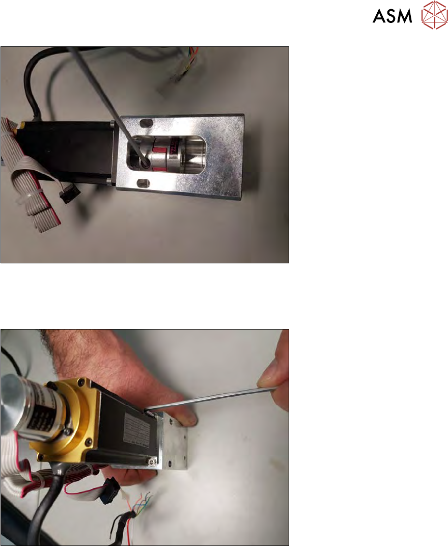
Fig.59:
► Remove the coupling clamping screw for the motor shaft.
You might need to widen the coupling clamp with a screwdriver.
► Pull the coupling off the motor shaft.
Fig.60:
► Remove the four screws fastening the motor to the coupling plate.
5 Basic frame – X/Y unit
5.3 Replacing parts
78 Service Manual SIPLACE Wafer System (SWS) 11/2018
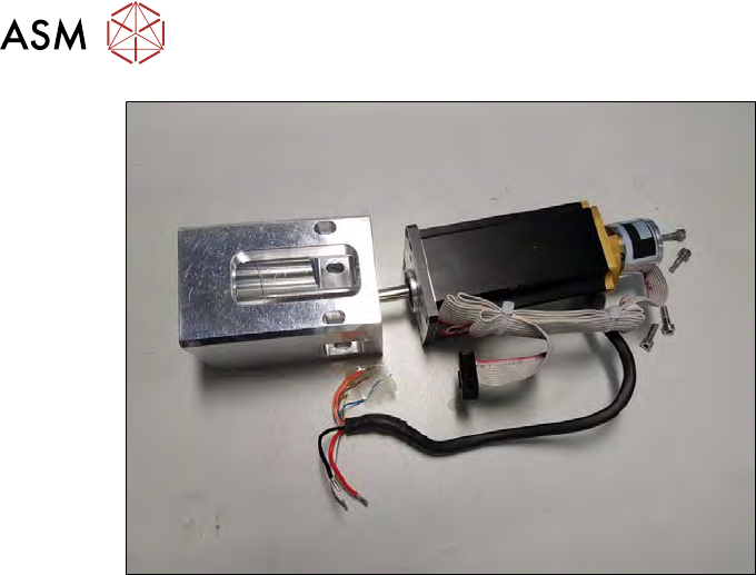
Fig.61:
The Y motor and coupling plate are now separate.
Pay attention to the position.