00195982-03_SM_SWS_EN.pdf - 第236页
10 Option Die Attach Unit SWS 10.1 Installing the Option Die Attach Unit SWS 236 Service Manual SIPLACE Wafer System (SWS) 11/2018 10.1.4.4 Storing the cables Fig.313: Cover and cable routing for SWS (2,4) in location 2…
10 Option Die Attach Unit SWS
10.1 Installing the Option Die Attach Unit SWS
Service Manual SIPLACE Wafer System (SWS) 11/2018 235
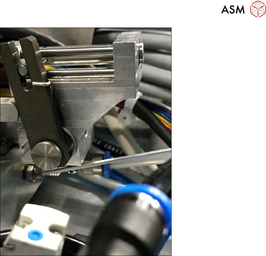
Fig.312:
► Adjust the jaw by turning the adjustment screw with a 1.5mm Allen key (see figure).
► If you cannot adjust the jaw position with the adjustment screw so that the ball bearing of seg-
ment 1 moves smoothly over the transfer X jaw, the jaw might be twisted with respect to the
flip head raceway. In that case, loosen the safety screws of the Die Attach Unit again (see
above).
► Move the Die Attach Unit then press it down. Tighten the three safety screws stepwise.
Sometimes, the Die Attach Unit is stuck on the alignment bolt. As a result, the Die Attach Unit
is slightly tilted and cannot be placed down onto the ground plate completely. In this case the
jaw of the transfer x axis is misaligned.
10 Option Die Attach Unit SWS
10.1 Installing the Option Die Attach Unit SWS
236 Service Manual SIPLACE Wafer System (SWS) 11/2018
10.1.4.4 Storing the cables
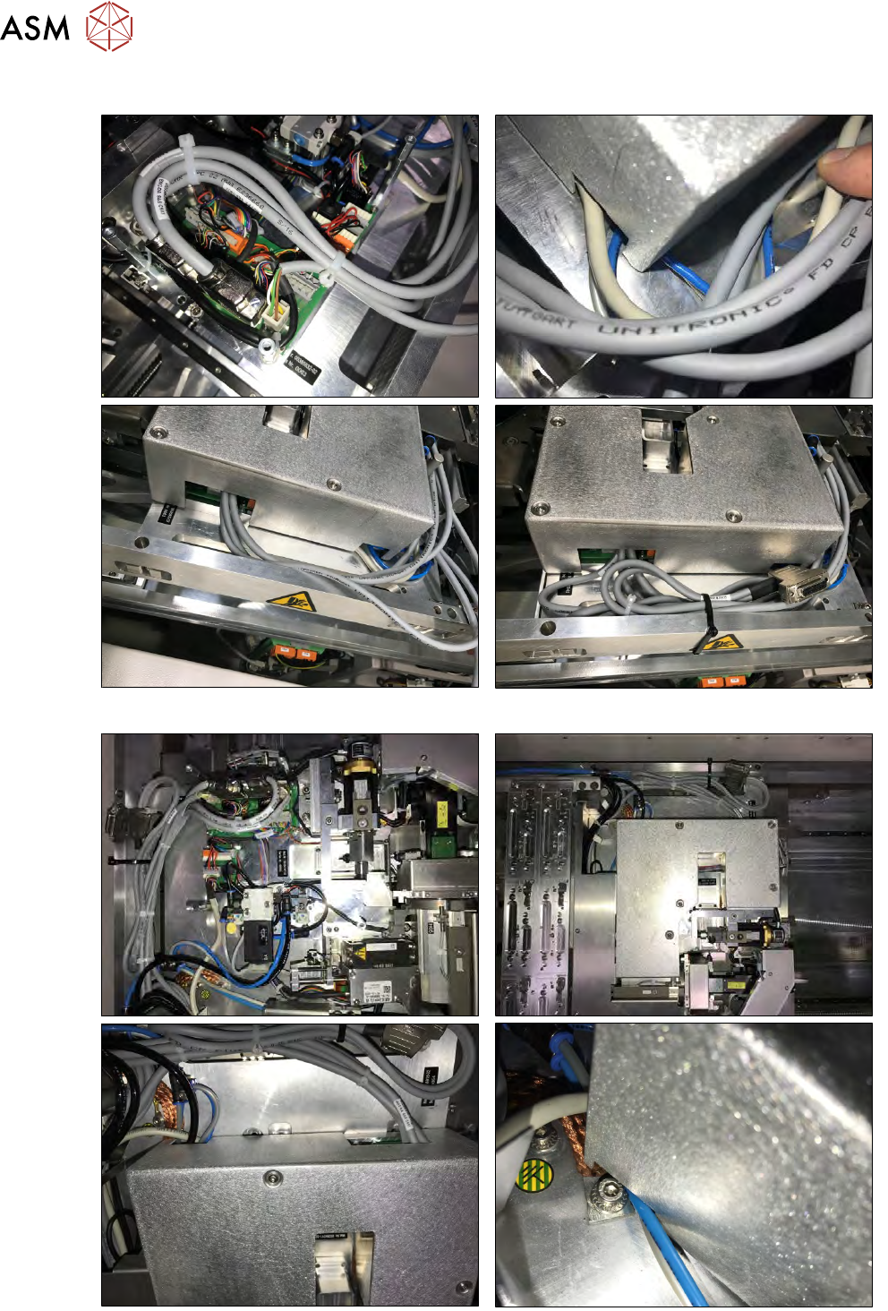
Fig.313: Cover and cable routing for SWS (2,4) in location 2 or 4.
Fig.314: Cover and cable routing for SWS (1, 3) in location 1 or 3.
10 Option Die Attach Unit SWS
10.1 Installing the Option Die Attach Unit SWS
Service Manual SIPLACE Wafer System (SWS) 11/2018 237
► Store and run the cables as shown in the figures.
Place the cover on the Die Attach Unit.
Make sure that no cables or tubes are clamped or damaged.
Tighten the screws of the Die Attach cover.
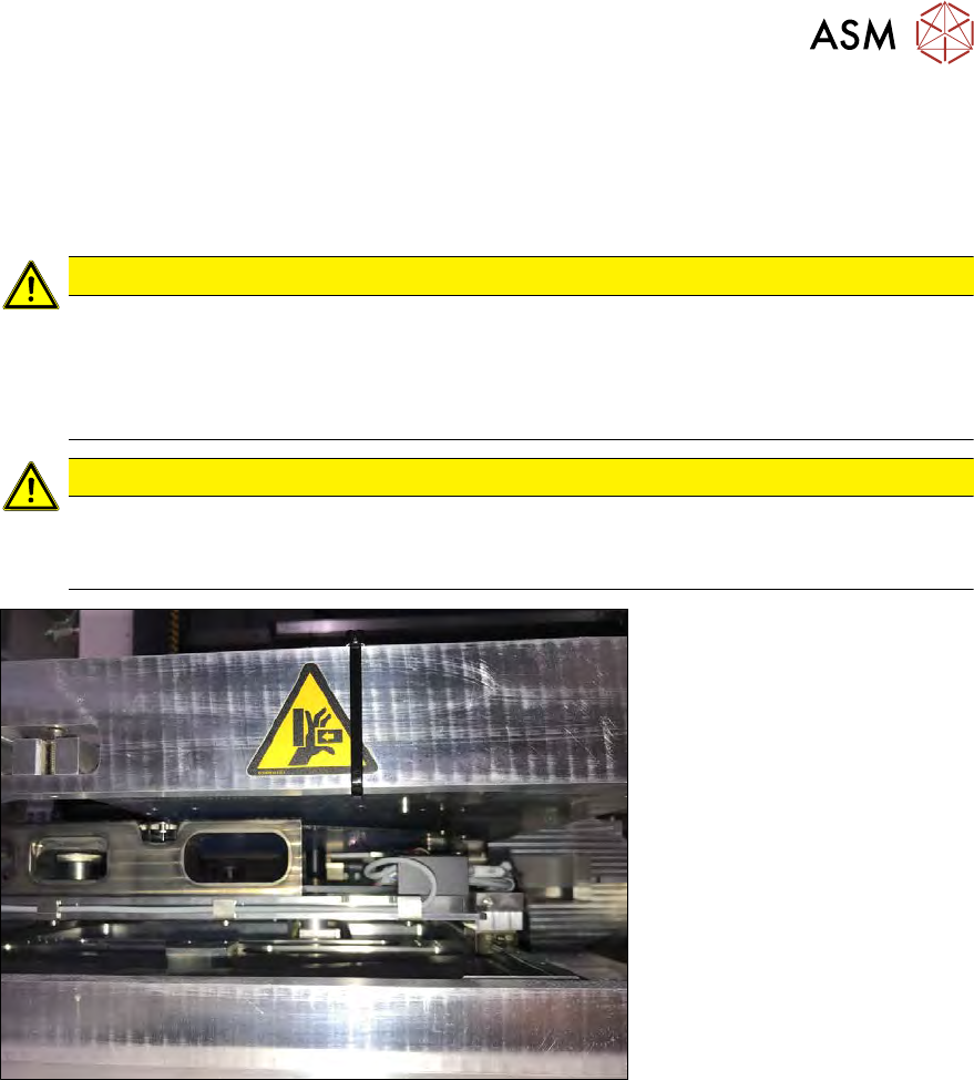
► Bind the cables outside the cover together using cable ties as shown in the figure.
CAUTION
Danger of Crash!
► Make sure that the Die Attach Unit cover is mounted correctly! Move the placement
head carefully over the Die Attach Unit and check whether there is enough clearance
between cover and placement head. Especially for SIPLACE C&P20 heads this is
very critical!
CAUTION
► Make sure that no cable is standing up that may crash with the placement head!
► Make sure that no cables are sagging beneath the ground plate. Otherwise, these
might crash with the wafer table!
Fig.315:
► After successful installation, the Die Attach Unit must be calibrated.