00195982-03_SM_SWS_EN.pdf - 第98页
5 Basic frame – X/Y unit 5.3 Replacing parts 98 Service Manual SIPLACE Wafer System (SWS) 11/2018 Fig.99: ► Wire the Hall sensor cable and power supply cable to the X motor. Pay attention to the correct wiring (see 5.3.…
5 Basic frame – X/Y unit
5.3 Replacing parts
Service Manual SIPLACE Wafer System (SWS) 11/2018 97
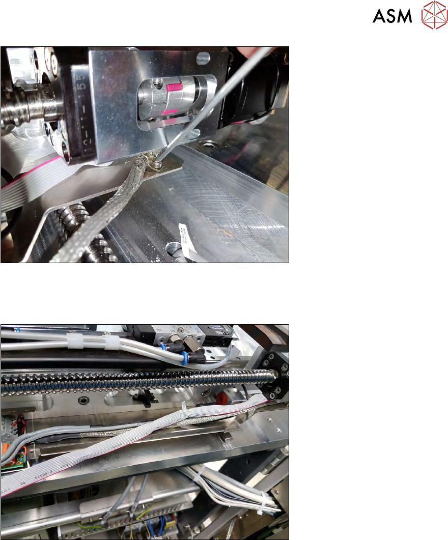
Fig.97:
► Lift the cable downholder over the shielded cable and carefully tighten the screw with the ball
head of the Allen key.
The cable should be aligned parallel to the X axis.
Fig.98:
► As shown in the diagram above, run the cable without twisting!
5 Basic frame – X/Y unit
5.3 Replacing parts
98 Service Manual SIPLACE Wafer System (SWS) 11/2018
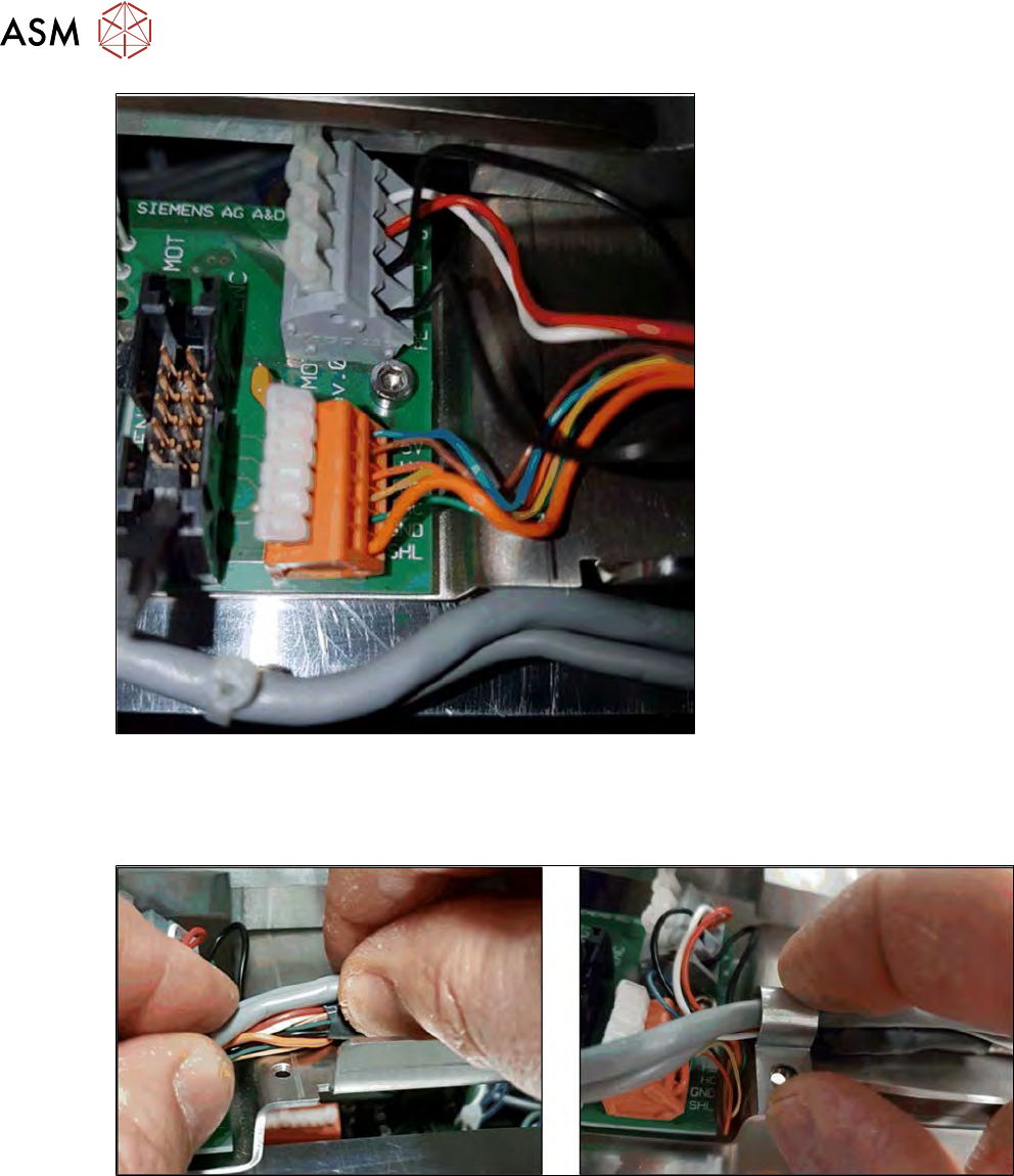
Fig.99:
► Wire the Hall sensor cable and power supply cable to the X motor.
Pay attention to the correct wiring (see 5.3.2.1 "Removing the X motor and coupling" [}85]).
► Connect the flat ribbon cable to the encoder.
Fig.100:
► Position the cable and fix it into place with a cable downholder.
► Screw the cable downholder into place. Make sure that you do not squash any cables!
5 Basic frame – X/Y unit
5.3 Replacing parts
Service Manual SIPLACE Wafer System (SWS) 11/2018 99
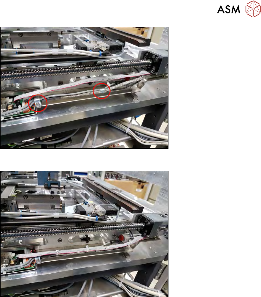
Fig.101:
► Fasten the second downholder into place.
Fig.102:
► Fasten the flat ribbon cable to the cables with cable ties.