00195982-03_SM_SWS_EN.pdf - 第253页
10 Option Die Attach Unit SWS 10.2 Dissambling Die-Attach-Unit SWS Service Manual SIPLACE Wafer System (SWS) 11/2018 253 Fig.346: Storing the cables after disassembly on SWS at location 2 or 4 CAUTION If the cables and …
10 Option Die Attach Unit SWS
10.2 Dissambling Die-Attach-Unit SWS
252 Service Manual SIPLACE Wafer System (SWS) 11/2018
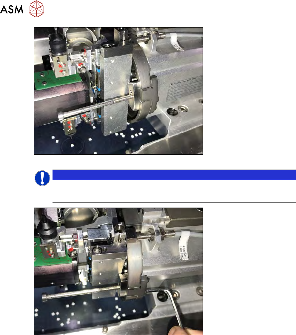
Fig.344:
NOTICE
► Cover the opening of the die ejector, e.g. with a cardboard (as a protection to prevent
damages should the gauge fall down). Do not forget to lift the cover off once you are
finished.
Fig.345:
► Gently tighten the two safety screws of the filling piece.
► Take the adjustment gauge out.
► Move the rotation axis of the flip head manually and make sure the bearing of the segment
moves smoothly over the filling piece.
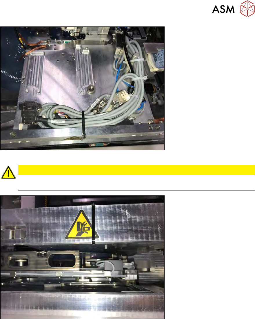
► The cables and tubes for the Die Attach Unit must be bound together with cable ties (see fol-
lowing figures).
– If the cables stand up, there will be a crash with the placement head!
– If the cables sag, they will be damaged by the wafer table!
10 Option Die Attach Unit SWS
10.2 Dissambling Die-Attach-Unit SWS
Service Manual SIPLACE Wafer System (SWS) 11/2018 253
Fig.346: Storing the cables after disassembly on SWS at location 2 or 4
CAUTION
If the cables and tubes for the Die Attach Unit are not stored and bound together, there is a
danger of crash with the wafer table and the placement head!
Fig.347:

10 Option Die Attach Unit SWS
10.2 Dissambling Die-Attach-Unit SWS
254 Service Manual SIPLACE Wafer System (SWS) 11/2018