00195982-03_SM_SWS_EN.pdf - 第171页
7 Die ejector 7.6 Converting the bayonet needle ejector unit (old version) to the magnetic needle ejector unit (current Service Manual SIPLACE Wafer System (SWS) 11/2018 171 7.6.3 Fitting the needle ejector unit magnetic…
7 Die ejector
7.6 Converting the bayonet needle ejector unit (old version) to the magnetic needle ejector unit (current
170 Service Manual SIPLACE Wafer System (SWS) 11/2018
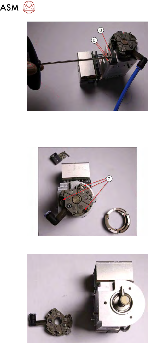
Fig.219:
► Remove the two screws (5) (Allen screw 2.5) fastening the fork light barrier board (6).
The cable to the fork light barrier does not need to be unplugged (the diagram without cable is
just an example).
► Pull the vacuum hose (blue) off.
Fig.220:
► Remove the three screws (7) (Allen screw 2.5) holding the base unit of the bayonet fastening.
Fig.221:
► Dismantle the base unit of the bayonet fastening.
7 Die ejector
7.6 Converting the bayonet needle ejector unit (old version) to the magnetic needle ejector unit (current
Service Manual SIPLACE Wafer System (SWS) 11/2018 171
7.6.3 Fitting the needle ejector unit magnetic table
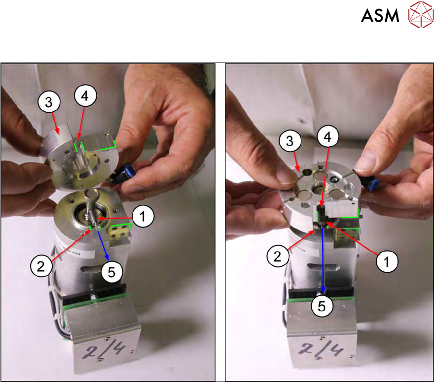
Fig.222:
► Observe the alignment of the switch flag (1) and the centering unit (3) to the Z axis of the die
ejector (direction (5))!
Make sure that the switch flag (1) is flush with the groove (2) in the housing of the Z axis for
the die ejector.
► Lift the centering unit (3) over the die ejector Z axis.
Make sure that the switch flag (1) points in the direction (5) of the groove (2).
► When positioning the centering unit (3), the switch flag (1) should fit into the groove (4) of the
centering unit and also into the groove(2) of the die ejector Z axis.
7 Die ejector
7.6 Converting the bayonet needle ejector unit (old version) to the magnetic needle ejector unit (current
172 Service Manual SIPLACE Wafer System (SWS) 11/2018
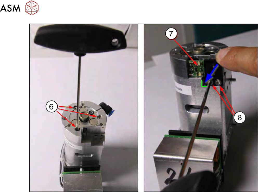
Fig.223:
The cable for the fork light barrier board does not need to be unplugged for removal (the diagram
without cable is just an example).
► Fasten the centering unit into place with the three Allen screws (6). Use the screws from the
unit you dismantled before.
► Fit the fork light barrier board (7) into place with the two Allen screws(8). Press the board into
the bottom left corner and tighten the two Allen screws.
► Connect the vacuum hose to the centering unit.
Calibrating
The following calibrations must be performed after the conversion.
●
Position "calibration of ejection needle"
This calibrates the height of the needle so that it is flush with the upper edge of the black ejec-
tion cap (see 15.3.2.5 "Calibration – die ejector needle" [}385]).
●
Check the needle position in the X and Y directions.
The needle tip must correspond with the camera center point (red cross in Vision view) (see
15.3.2.4 "Calibration – segment offset calibration in X direction" [}379]).