00195982-03_SM_SWS_EN.pdf - 第90页
5 Basic frame – X/Y unit 5.3 Replacing parts 90 Service Manual SIPLACE Wafer System (SWS) 11/2018 Fig.83: ► Pull the X motor, together with the coupling plate, away towards the back and lift the unit up and out! Fig.84…
5 Basic frame – X/Y unit
5.3 Replacing parts
Service Manual SIPLACE Wafer System (SWS) 11/2018 89
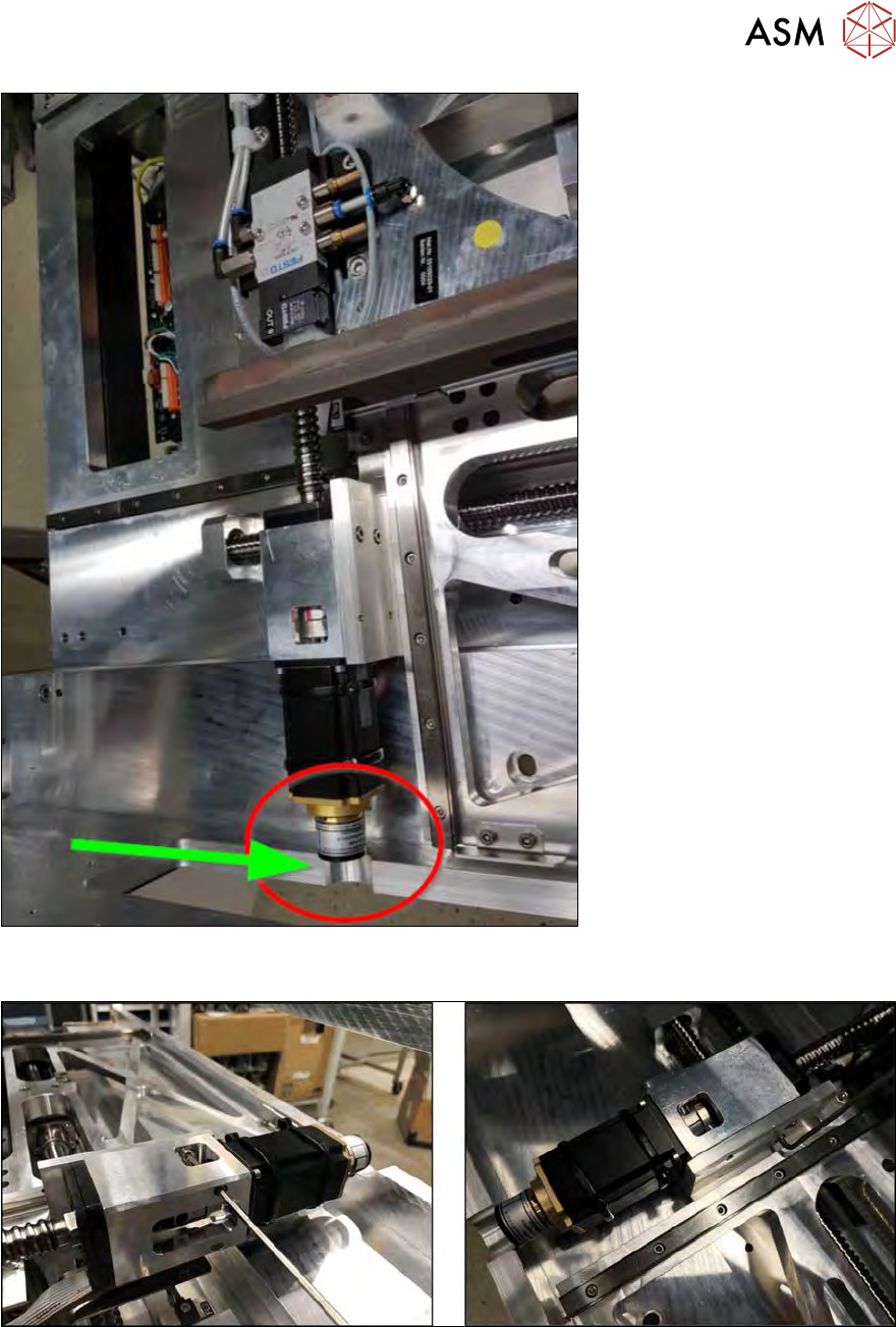
Fig.81:
► Move the wafer table until the X motor is level with the semicircular recess in the side frame.
Fig.82:
► Now remove the two screws fastening the front of the coupling housing.
► Remove the two fastening screws on the back with a short (modified) Allen key.
5 Basic frame – X/Y unit
5.3 Replacing parts
90 Service Manual SIPLACE Wafer System (SWS) 11/2018
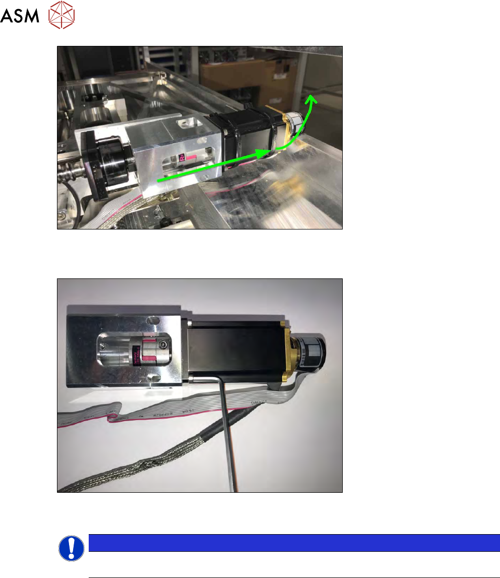
Fig.83:
► Pull the X motor, together with the coupling plate, away towards the back and lift the unit up
and out!
Fig.84:
► Remove the four screws fastening the motor.
NOTICE
You do not necessarily need to remove the cable ties fixing the motor cable to the motor
housing.
5 Basic frame – X/Y unit
5.3 Replacing parts
Service Manual SIPLACE Wafer System (SWS) 11/2018 91
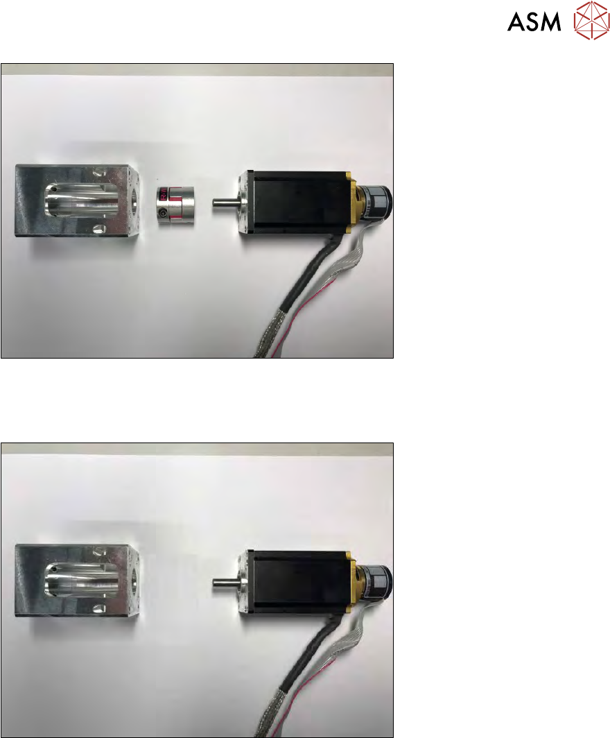
Fig.85:
Coupling plate, coupling and X motor are now separate and can be replaced.
5.3.2.2 Fitting the new X motor and coupling
Fig.86:
► Fit the new X motor onto the coupling plate.
Make sure that the motor cable, as shown in the photo, points at 90° downwards to the coup-
ling plate!
Leave the coupling to one side at the moment. This will be inserted into the coupling plate
later on.
You might need to fasten the motor cable to the motor housing with two cable ties.