00195982-03_SM_SWS_EN.pdf - 第274页
12 Wafer stretcher 12.2 Detailed description of "wafer stretching" procedure 274 Service Manual SIPLACE Wafer System (SWS) 11/2018 Fig.375: ● The die ejector needle is moved in. Fig.376: ● The die ejector is …
12 Wafer stretcher
12.2 Detailed description of "wafer stretching" procedure
Service Manual SIPLACE Wafer System (SWS) 11/2018 273
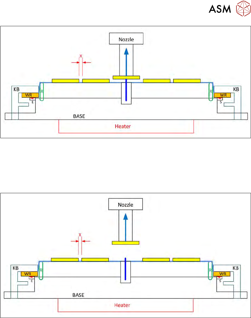
Fig.373:
●
Once the nozzle touches the die, the vacuum present causes the die to adhere to the nozzle.
●
The die ejector needle now moves upwards and lifts the die off the foil.
●
The flip unit Z axis now synchronously moves the die ejector needle upwards for the ejection
process.
●
The die is held on the nozzle by the vacuum.
Fig.374:
●
The die is fully released from the wafer foil.
●
The Z axis of the flip unit moves right up and the component picked up can be processed by
the CA machine.
12 Wafer stretcher
12.2 Detailed description of "wafer stretching" procedure
274 Service Manual SIPLACE Wafer System (SWS) 11/2018
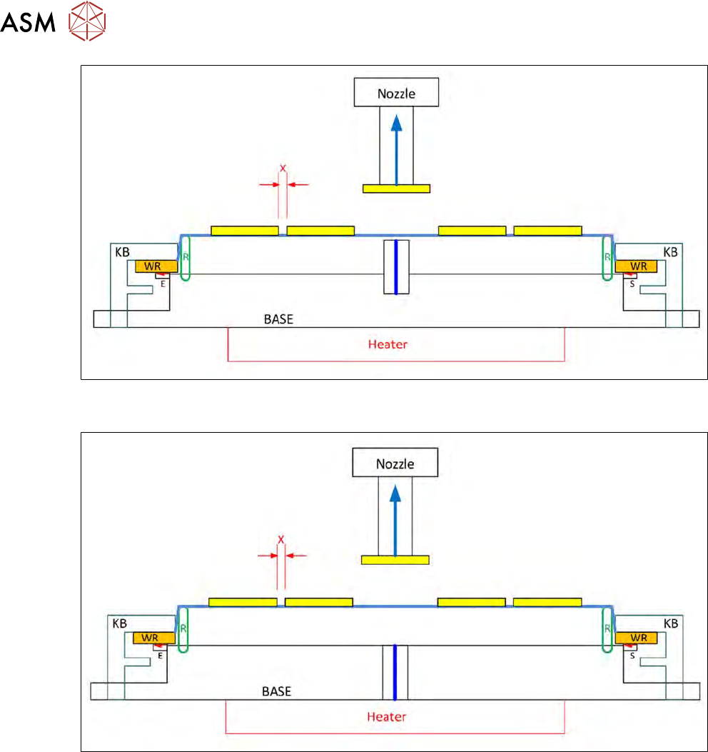
Fig.375:
●
The die ejector needle is moved in.
Fig.376:
●
The die ejector is moved back into the base (BASE).
12 Wafer stretcher
12.2 Detailed description of "wafer stretching" procedure
Service Manual SIPLACE Wafer System (SWS) 11/2018 275
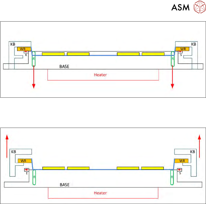
Fig.377:
●
The clamping ring (R) is moved downwards again.
●
The wafer foil is now sagging. (Actually, it is concave but for technical drawing purposes it is
straight.)
Fig.378:
●
The clamping plate (KB) is moved upwards again.
●
The wafer frame (WR) is positioned again on the support strip of the clamping plate (KB).
●
The wafer foil is still sagging. (Actually, it is concave but for technical drawing purposes it is
straight.)