00195982-03_SM_SWS_EN.pdf - 第276页
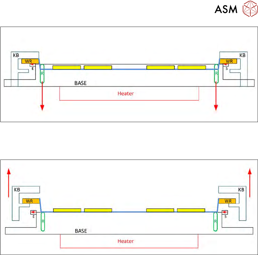
12 Wafer stretcher 12.2 Detailed description of "wafer stretching" procedure 276 Service Manual SIPLACE Wafer System (SWS) 11/2018 Fig.379: ● The sag sensor IN19 ( S = transmitter / E = receiver) is switched o…
12 Wafer stretcher
12.2 Detailed description of "wafer stretching" procedure
Service Manual SIPLACE Wafer System (SWS) 11/2018 275
Fig.377:
●
The clamping ring (R) is moved downwards again.
●
The wafer foil is now sagging. (Actually, it is concave but for technical drawing purposes it is
straight.)
Fig.378:
●
The clamping plate (KB) is moved upwards again.
●
The wafer frame (WR) is positioned again on the support strip of the clamping plate (KB).
●
The wafer foil is still sagging. (Actually, it is concave but for technical drawing purposes it is
straight.)
12 Wafer stretcher
12.2 Detailed description of "wafer stretching" procedure
276 Service Manual SIPLACE Wafer System (SWS) 11/2018
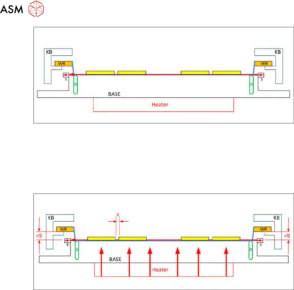
Fig.379:
●
The sag sensor IN19 (S = transmitter / E = receiver) is switched on.
●
The light beam is sent from the transmitter to the receiver.
●
If a light is received by the receiver, this means that the foil is not sagging so much that it
would rub against the base (BASE) when the wafer frame is pulled back in the wafer lift,
thereby breaking the wafer foil!
●
The top diagram shows that the light beam has been interrupted due to excessive sagging of
the wafer foil.
Fig.380:
●
The heating (heater) is switched on.
●
This warms the wafer foil, which then shrinks together again.
●
This reduces the stretch.
●
The space between the dies is reduced (X).
●
The wafer foil sag is also reduced.
●
If the sag is still more than 9 mm, the sag sensor IN 19 will not emit a signal.
12 Wafer stretcher
12.2 Detailed description of "wafer stretching" procedure
Service Manual SIPLACE Wafer System (SWS) 11/2018 277
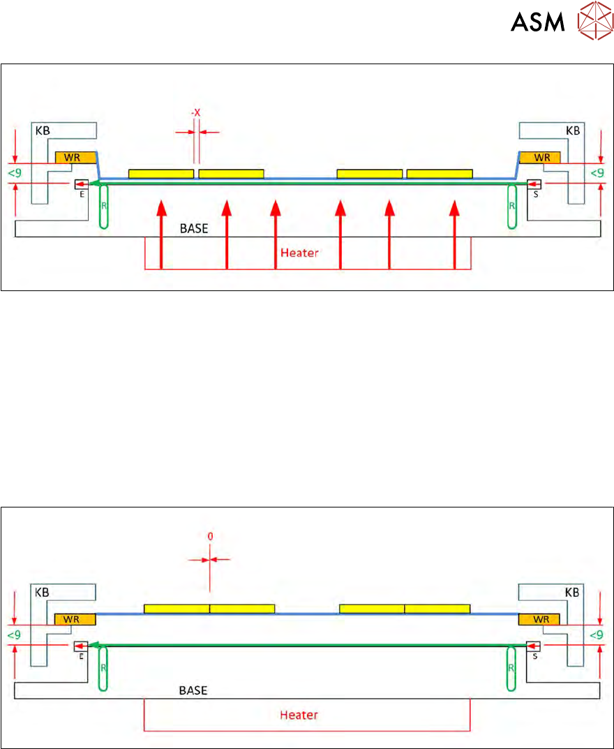
Fig.381:
●
The heating (heater) is still active and warms the wafer foil.
●
This increasingly shrinks together.
●
The space between the dies is reduced (-X).
●
The sagging wafer foil now no longer interrupts the light beam from the transmitter (S) of the
sag sensor.
●
The light arrives at the receiver (E).
●
The receiver (E) emits the IN19 signal indicating that the wafer foil is no longer sagging.
●
The wafer frame can now be changed in the wafer lift without the risk of the base being
touched.
Fig.382:
●
In an ideal case, the wafer foil will have shrunk back to its original stretch state.
●
The space between the dies is now near to 0.