00195982-03_SM_SWS_EN.pdf - 第134页
7 Die ejector 7.3 Replacing spare parts 134 Service Manual SIPLACE Wafer System (SWS) 11/2018 Fig.159: ► Remove the board holder from the motor. CAUTION Screws ► Make sure that the two screws (M3x14) for fastening the b…
7 Die ejector
7.3 Replacing spare parts
Service Manual SIPLACE Wafer System (SWS) 11/2018 133
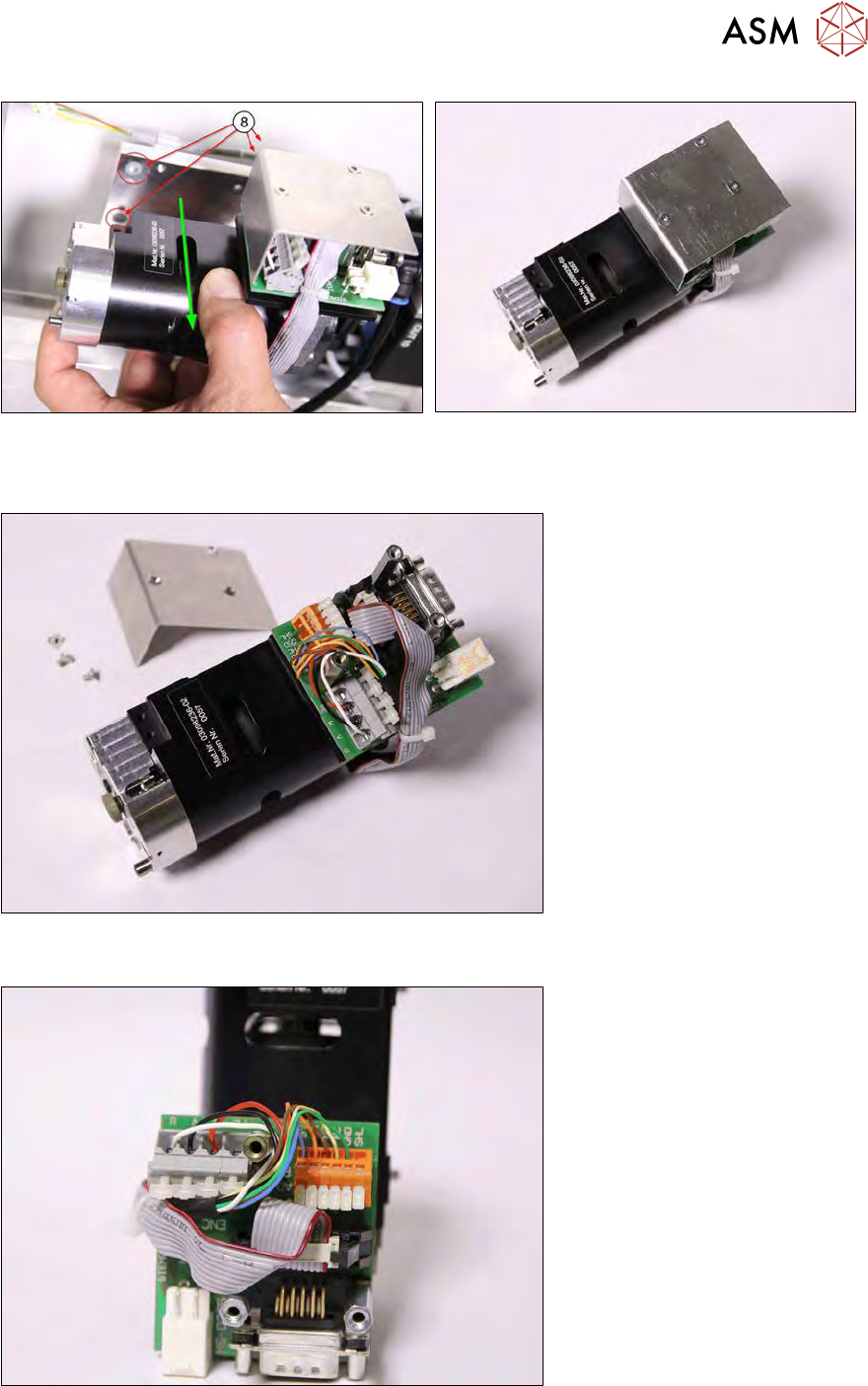
Fig.155: Pulling off
Fig.156: Dismantled Z axis die ejector
► Pull off the Z axis die ejector. Make sure that the four loss prevention locks (8) do not fall out
(diagram shows two visible and two covered).
Fig.157:
► Remove the board cover.
Fig.158:
► Disconnect all cables (small screwdriver).
► Disconnect the encoder signal (ENC).
7 Die ejector
7.3 Replacing spare parts
134 Service Manual SIPLACE Wafer System (SWS) 11/2018
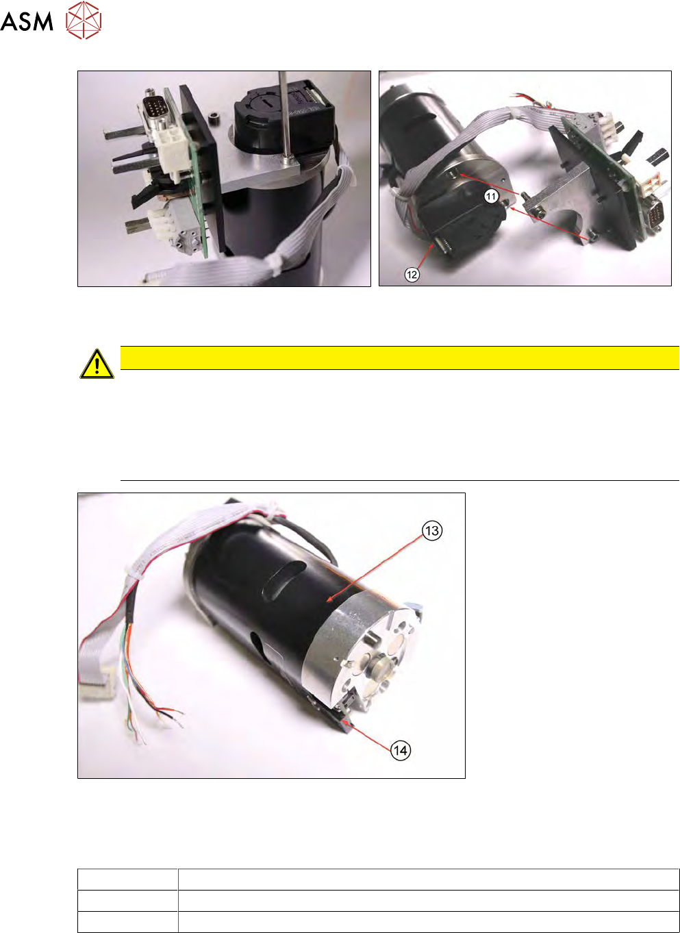
Fig.159:
► Remove the board holder from the motor.
CAUTION
Screws
► Make sure that the two screws (M3x14) for fastening the board holder(11) are longer
than the covered third screw(12) on the motor cover (M3x10).
► The new Z axis die ejector [03098367-xx]/[03098368-xx] is supplied without the board
holder. All three motor cover screws are therefore short ones (M3x10). Please always
use long screws to fit the board holder (M3x14)!
Fig.160:
The assembly has now been completely removed.
The Z axis die ejector assembly (13) is supplied inclusive of the dual light barrier board (14). The
diagram shows the dual light barrier board refitted.
03098367-xx Z axis die ejector (2,4), magnetic
03098236-xx Z axis die ejector (1,3), magnetic
00385741-xx Dual light barrier board 27.5 x14mm
The dual light barrier board [00385741-xx] can also be ordered separately.
7 Die ejector
7.3 Replacing spare parts
Service Manual SIPLACE Wafer System (SWS) 11/2018 135
7.3.4 Fitting the Z axis on the die ejector
Preconditions
●
SWS removed from machine
●
SWS disconnected from the power supply
Procedure
To fit the Z axis onto the die ejector, follow the removal instructions in reverse order (see 7.3.3 "Re-
moving the Z axis from the die ejector" [}129]).
The Z axis die ejector assembly magnetic table [03098367-xx]/[03098368-xx] is supplied inclusive
of the dual light barrier board [00385741‑xx]!
Before fitting the Z axis onto the die ejector, we recommend dismantling the fork light barrier (dual
light barrier board and assembly bracket):
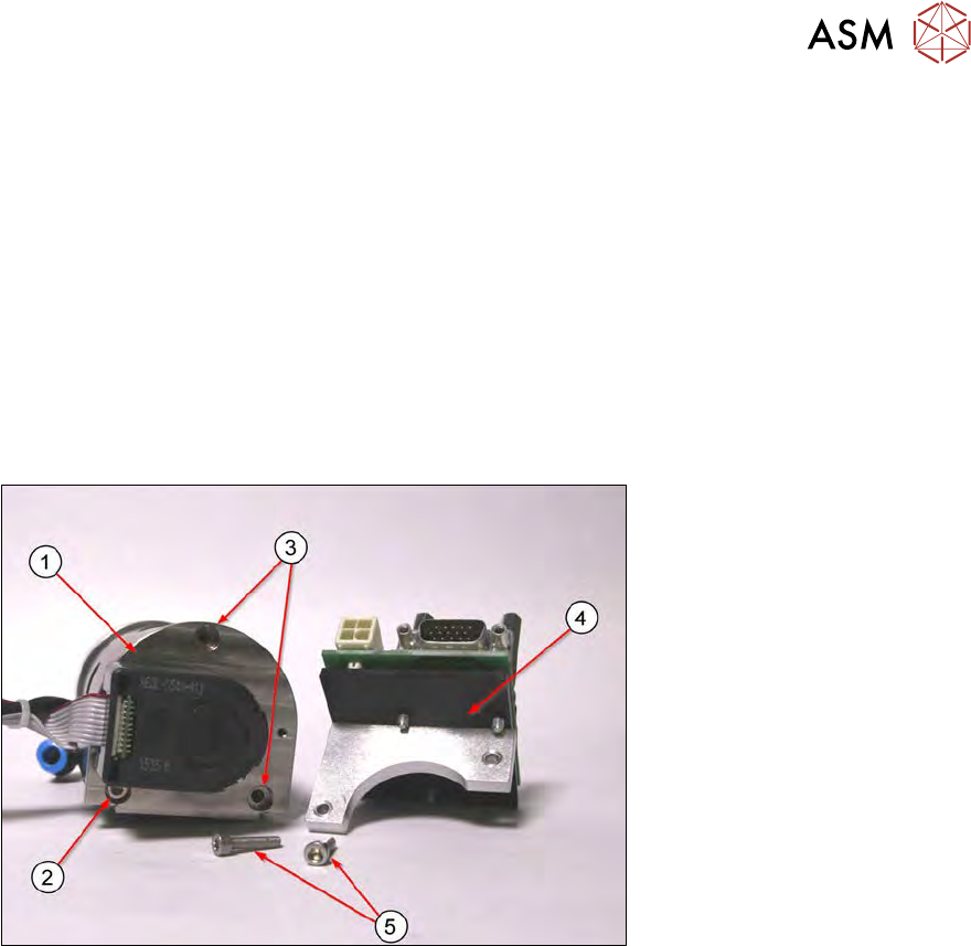
Fig.161: Z axis die ejector [03098367-xx] for an SWS 2/4
► Remove the two short M3x10 screws (3) and leave the screw (2) on the Z axis die ejector
assembly(1).
The diagram shows a Z axis die ejector [03098367-xx] for an SWS 2/4 (1). The Z axis die ejector
[03098367‑xx] for the SWS 1/3 has the rotary encoder for the motor rotated by 180°. In this case,
the board holder needs to be fitted accordingly(4).
► Fit the board holder (4) with two M3x14 screws(5) to the positions(3) in the motor cover.