00195982-03_SM_SWS_EN.pdf - 第41页
2 Overview of the SIPLACE wafer system (SWS) 2.4 Description of SWS assemblies Service Manual SIPLACE Wafer System (SWS) 11/2018 41 2.4.2 Optional features 2.4.2.1 Linear dipping unit (LDU) Fig.22: Linear dipping unit (…
2 Overview of the SIPLACE wafer system (SWS)
2.4 Description of SWS assemblies
40 Service Manual SIPLACE Wafer System (SWS) 11/2018
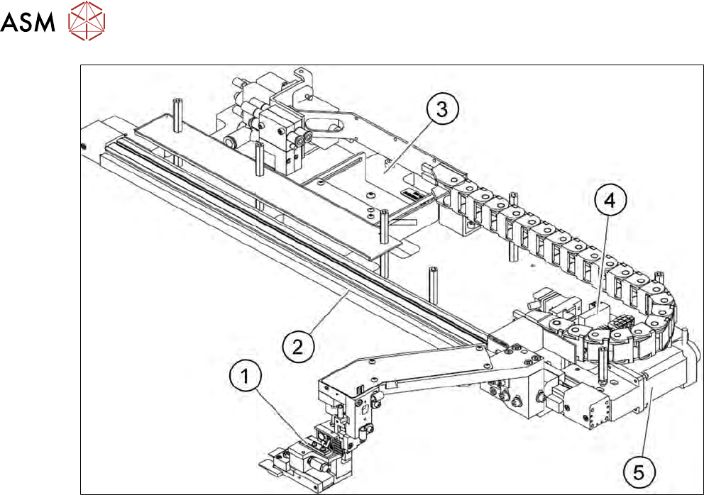
Fig.21: Main gripper assemblies (location 1/3)
1. Gripper
2. Toothed belt axis
3. Installation location for barcode scanner (optional)
4. AD-MOT board
5. Motor with coupling
2 Overview of the SIPLACE wafer system (SWS)
2.4 Description of SWS assemblies
Service Manual SIPLACE Wafer System (SWS) 11/2018 41
2.4.2 Optional features
2.4.2.1 Linear dipping unit (LDU)
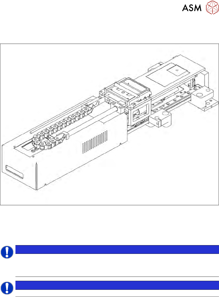
Fig.22: Linear dipping unit (LDU)
The LDU is needed to apply flux to the die during the flip chip process. This is necessary for ensur-
ing that the reflow process functions properly.
The LDU is able to apply highly accurate layers of flux. This flux is made available in a so-called
cavity. The depth of the cavity determines the thickness of the flux layer.
NOTICE
The LDU is, in principle, suitable for all types of flip chip flux.
► Only use epoxide and solder pastes after internal factory tests have been performed.
► If in doubt, contact the SIPLACE service team.
NOTICE
► Do not use the the LDU together with the die attach unit.
2 Overview of the SIPLACE wafer system (SWS)
2.4 Description of SWS assemblies
42 Service Manual SIPLACE Wafer System (SWS) 11/2018
2.4.2.2 Die attach unit
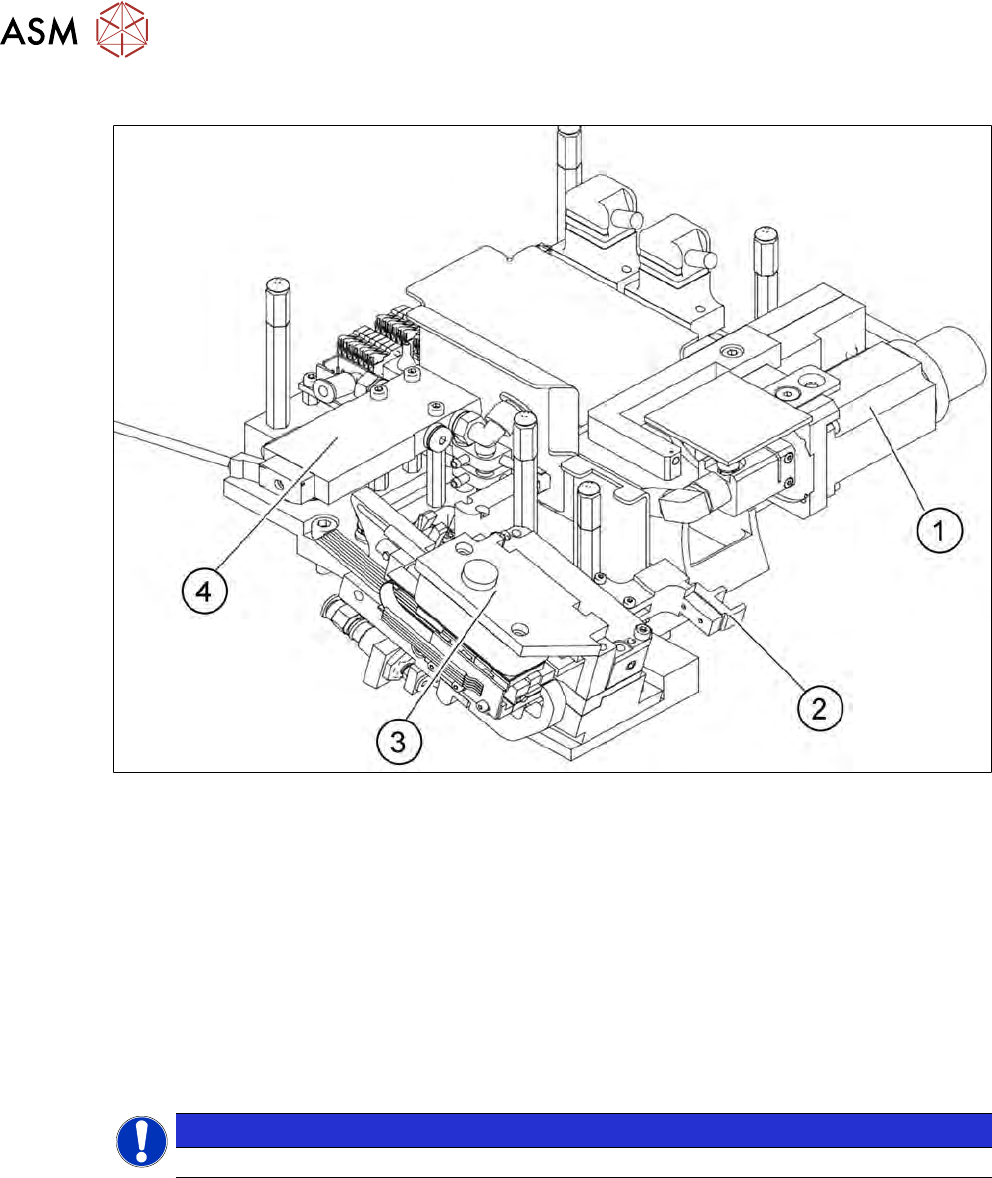
Fig.23: Die attach unit
1. Drive motor for rotation of die attach unit
2. Driver
3. Motor transfer X axis
4. Solenoid valve
The die attach unit is needed for die attach mode.
The flip unit transfers the die to the die attach unit. The die is then rotated accordingly there and
made available for pickup. The die is therefore made available to the placement head in the same
top/bottom orientation as it was on the wafer and is placed in this position.
In die attach mode, only one nozzle of the flip unit functions. The flip unit takes up the next die,
while the current die is being picked up by the placement head from the die attach unit.
NOTICE
► Do not use the die attach unit together with the LDU.
2.4.2.3 Small die kit
The small die kit is used when you need to process dies which are smaller than 1 mm. It is avail-
able as an option on request and consists of the following parts:
●
A high-resolution camera system
●
A small die ejector tool
●
A component sensor