00195982-03_SM_SWS_EN.pdf - 第201页
9 Wafer change system 9.2 Gripper Service Manual SIPLACE Wafer System (SWS) 11/2018 201 9.2 Gripper ● Gripper SWS12 (1/3) [00387108-xx] ● Gripper SWS12 (2/4) [00385525-xx] 9.2.1 Overview of main assemblies Fig.260: Main…
9 Wafer change system
9.1 Magazine lift
200 Service Manual SIPLACE Wafer System (SWS) 11/2018
9.1.2 Electrical system
NOTICE
Observe the circuit diagrams.
For details of the electrical assemblies on the wafer lift, please refer to the circuit diagrams
[00195960‑xx].
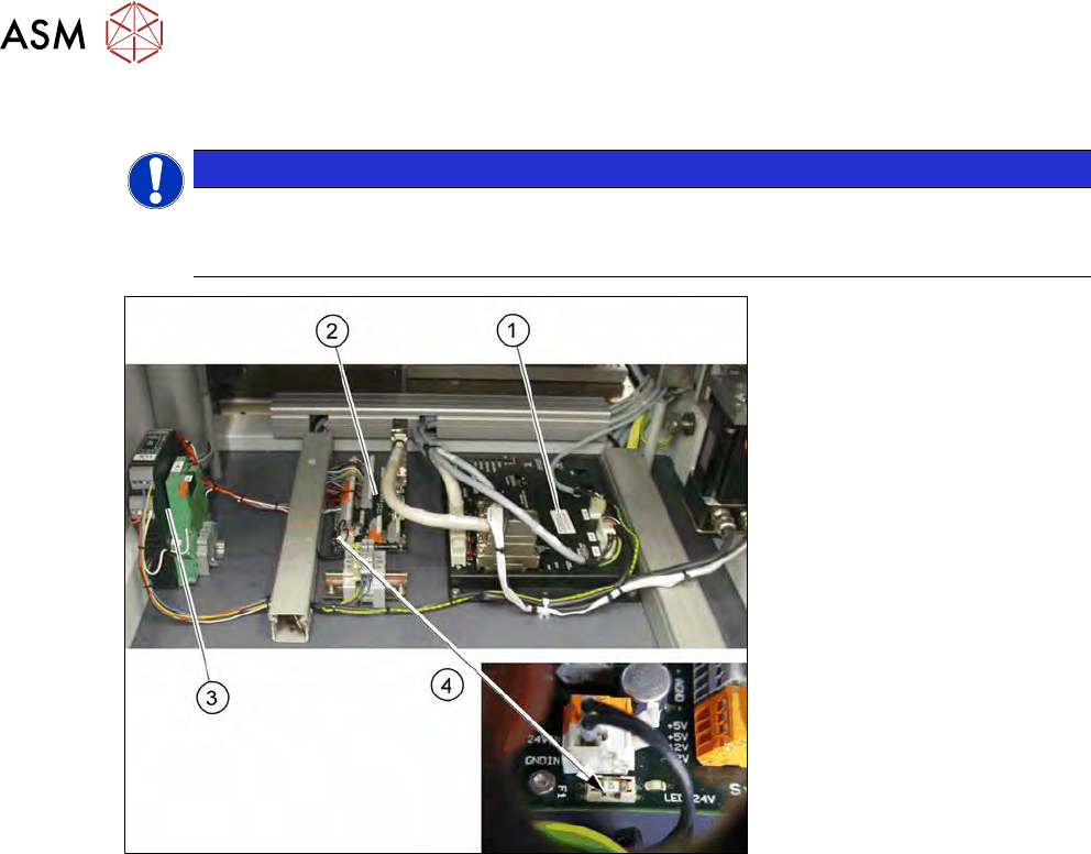
Fig.259: Electrics down on the wafer lift (overview)
1. Amplifier module 2-axes AMP-19520
2. Board DMC interface input/output
3. Protective contactor combination with optoelectronic coupler
4. Fuse 3 AT on the board DMC interface
9 Wafer change system
9.2 Gripper
Service Manual SIPLACE Wafer System (SWS) 11/2018 201
9.2 Gripper
●
Gripper SWS12 (1/3) [00387108-xx]
●
Gripper SWS12 (2/4) [00385525-xx]
9.2.1 Overview of main assemblies
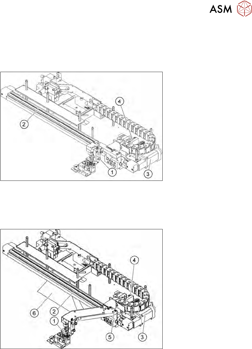
Fig.260: Main gripper assemblies (location 2/4)
1. Gripper
2. Toothed belt axis
3. Motor with coupling
4. AD-MOT board under the cover
Fig.261: Main gripper assemblies (location 1/3)
5. Gripper
6. Toothed belt axis
7. Motor with coupling
8. AD-MOT board
9. Height adjustment
10. Barcode scanner (optional)
9 Wafer change system
9.2 Gripper
202 Service Manual SIPLACE Wafer System (SWS) 11/2018
9.2.2 Overview of spare parts
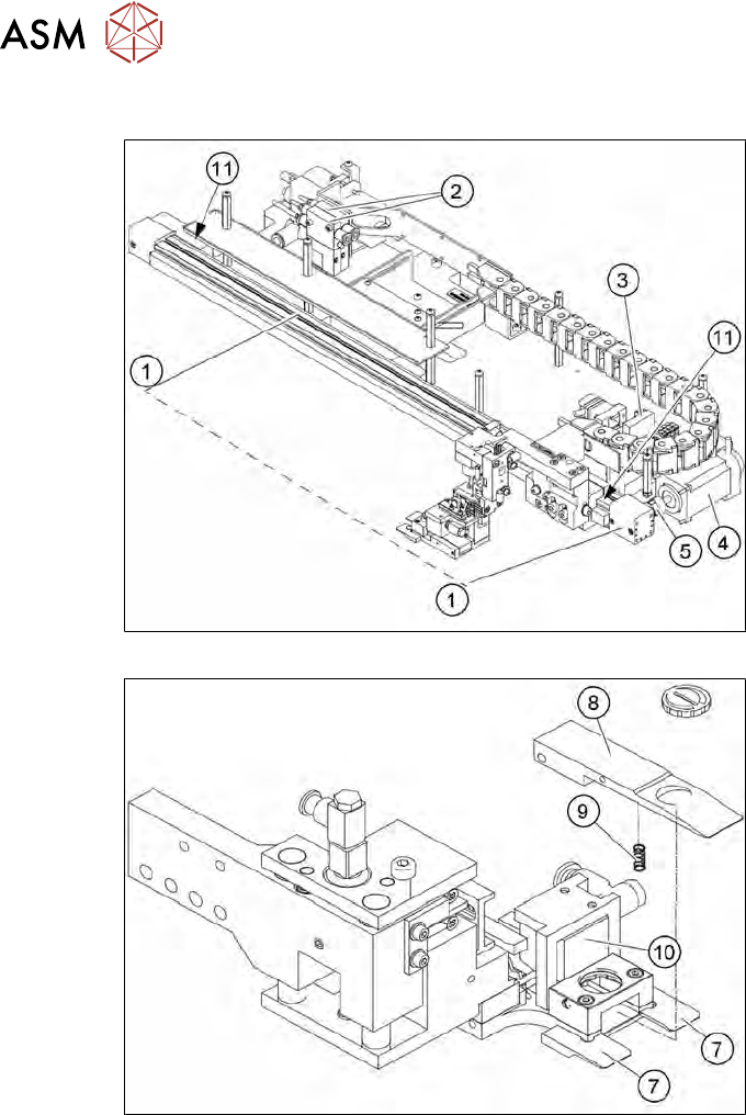
Fig.262: Spare parts on the gripper unit (example for location 2/4)
Fig.263: Spare parts on the gripper (for location 2/4)