00195982-03_SM_SWS_EN.pdf - 第162页
7 Die ejector 7.5 Mechanical adjustment of the die ejector unit in the Z direction (focus) 162 Service Manual SIPLACE Wafer System (SWS) 11/2018 7.5.1.5 Replacing the sealing unit and the O-ring on the die ejector center…
7 Die ejector
7.5 Mechanical adjustment of the die ejector unit in the Z direction (focus)
Service Manual SIPLACE Wafer System (SWS) 11/2018 161
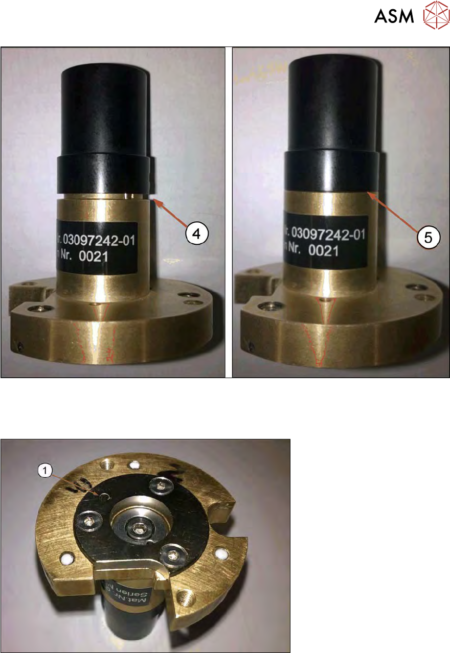
Fig.206:
► Check the black cap. This must be seated fully on the base unit of the ejection system.
(4) Gap → vacuum leakage → bad
(5) No gap → good
Fig.207:
► Check the polished sealing surface and the ejection system vacuum hole(1) for damage or
dirt.
7 Die ejector
7.5 Mechanical adjustment of the die ejector unit in the Z direction (focus)
162 Service Manual SIPLACE Wafer System (SWS) 11/2018
7.5.1.5 Replacing the sealing unit and the O-ring on the die ejector centering unit
The following description is explained using the new needle ejector unit (magnetic). The procedure
is identical for the needle ejector unit with the bayonet fastening.
Parts
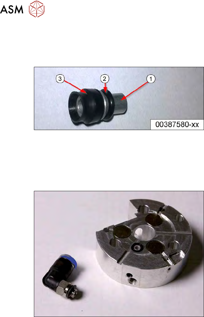
Fig.208:
The following spare parts are available:
●
[00387580-xx] Sealing unit
(suction adapter (1) incl. vacuum suction unit (2) and O-ring (3) prefitted)
●
[00201141-xx] O-ring 3*1 NBR 70 B (defined as maintenance/wear part)
Procedure
Fig.209:
► Remove the pneumatic connection using a fork wrench. Pay attention to the seals.
7 Die ejector
7.5 Mechanical adjustment of the die ejector unit in the Z direction (focus)
Service Manual SIPLACE Wafer System (SWS) 11/2018 163
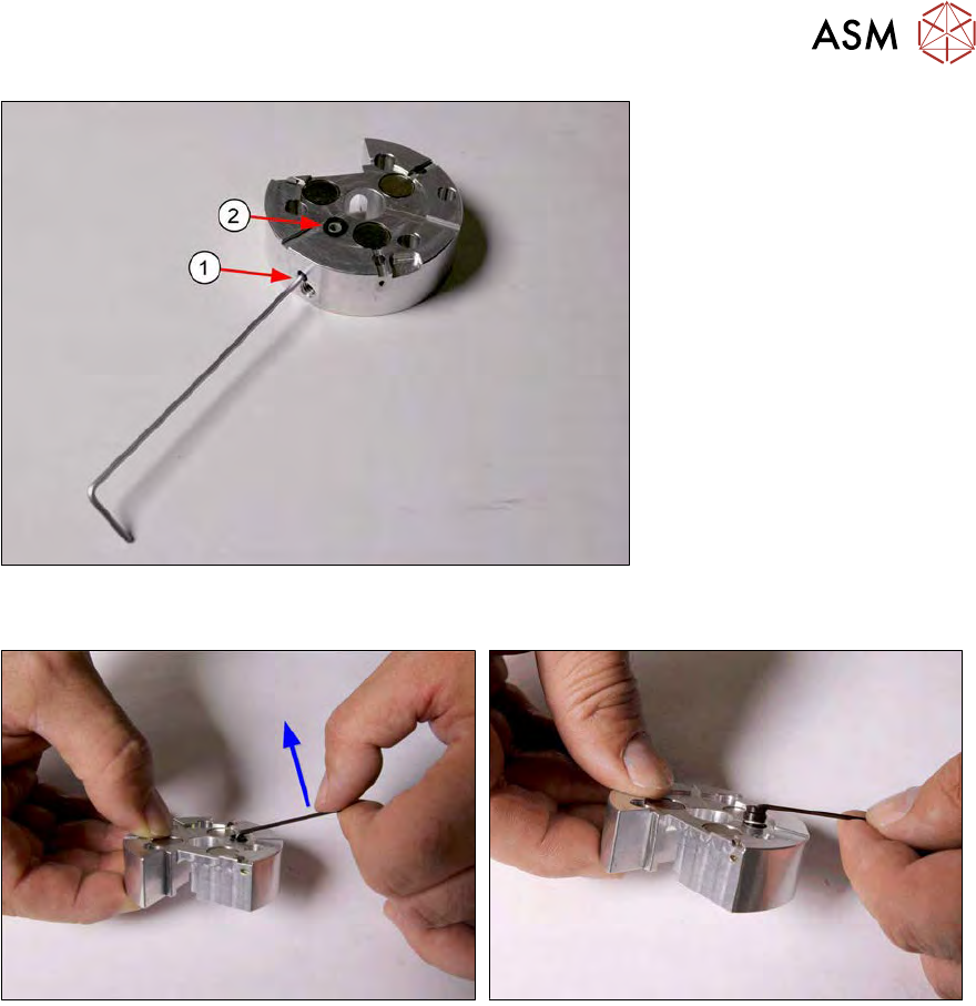
Fig.210:
► Loosen or remove the grub screw (1) (Allen key 1.5) fixing the sealing unit(2).
Fig.211:
► Pull the sealing unit up and out.
If it is not possible to pull the sealing unit out, clamp a small Allen key into the sealing unit
drilled hole and try to pull it up.
► It should then be possible to remove the sealing unit.
► Take the new compete sealing unit and grease the O-ring with UNISILCON L250L (thin layer
of lubricant).