00195982-03_SM_SWS_EN.pdf - 第168页
7 Die ejector 7.6 Converting the bayonet needle ejector unit (old version) to the magnetic needle ejector unit (current version) 168 Service Manual SIPLACE Wafer System (SWS) 11/2018 7.6 Converting the bayonet needle eje…
7 Die ejector
7.5 Mechanical adjustment of the die ejector unit in the Z direction (focus)
Service Manual SIPLACE Wafer System (SWS) 11/2018 167
7.5.4 Replacing the fork light barrier on the ejection system
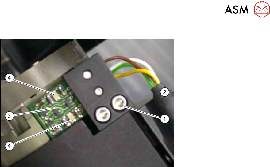
Fig.215: Fork light barrier on the ejection system (detailed view)
The fork light barrier on the ejection system monitors whether the needles are moved in or out. Two
LEDs(4) shine red on the board if the needles are moved out. When the fork light barrier is in its
neutral position, the LEDs will not shine.
► Remove the two fastening screws (1) and then remove the board (3) together with the black
bracket.
► Unplug the connection cable (2) from the board.
► Remove the two screwsfastening the board.
► Fit the new board onto the black bracket. The board must be fitted flush on the motor base
unit.
► Plug in the connection cable and screw the board with the black bracket back into place on
the ejection system.
► Check the input signals.
► Go to the toolbar and select the button Service Settings → Motor settings (see 14.1 "SWS
GUI - service settings" [}357]).
► Select the button GallilMotion_axis2 and then the tab Axis status.
ð The displays shine:
– Forward Limit active
– Reverse Limit active
► Select Initialize axis.
ð The Reverse Limit active view will shine briefly. → All OK.
7 Die ejector
7.6 Converting the bayonet needle ejector unit (old version) to the magnetic needle ejector unit (current
version)
168 Service Manual SIPLACE Wafer System (SWS) 11/2018
7.6 Converting the bayonet needle ejector unit (old version)
to the magnetic needle ejector unit (current version)
In the event of a defect occurring in the old needle ejector unit with bayonet fastening, you will need
to convert to the new ejector unit with magnet.
●
Conversion kit (on request)
Necessary tools
●
Standard Allen key kit
●
Allen key 1.27mm / 1.5mm
7.6.1 Preparatory measures
► Move the wafer table to the change position.
► Move the die ejector Z axis upwards.
The following conversion takes place in the machine. All following diagrams are examples.
7.6.2 Removing the bayonet needle ejector unit.
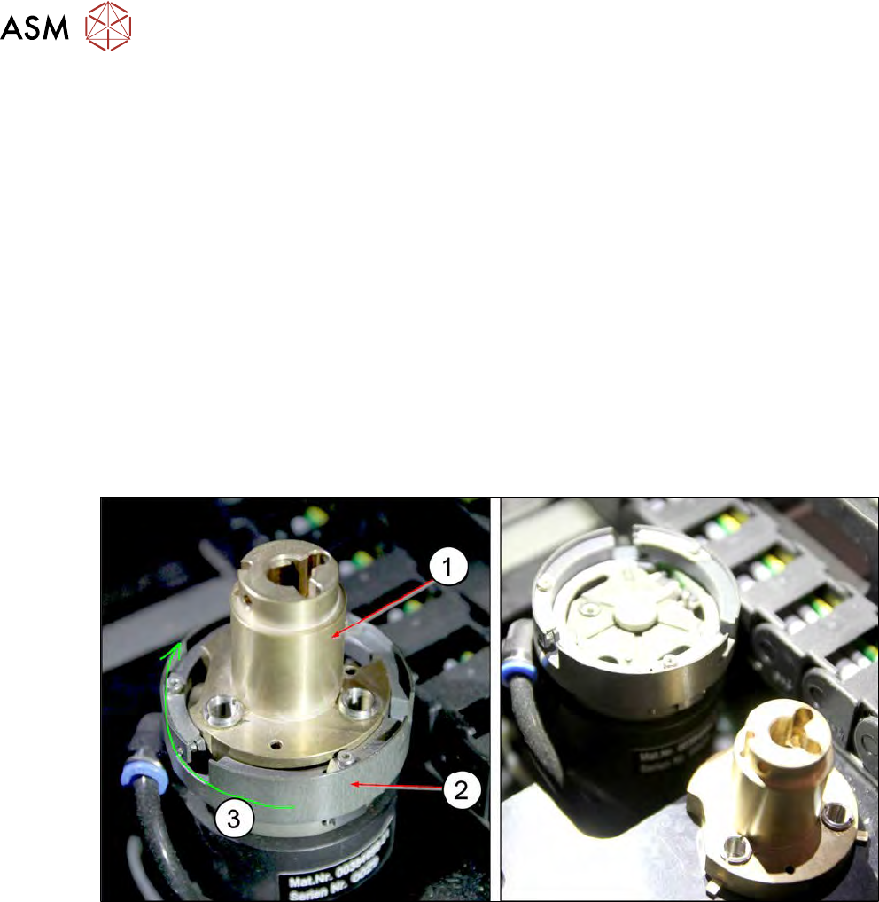
Fig.216:
► Unlock the bayonet ring (2) with a rotation to the right (3) (clockwise) and pull the needle
ejector unit(1) up and off.
7 Die ejector
7.6 Converting the bayonet needle ejector unit (old version) to the magnetic needle ejector unit (current
version)
Service Manual SIPLACE Wafer System (SWS) 11/2018 169
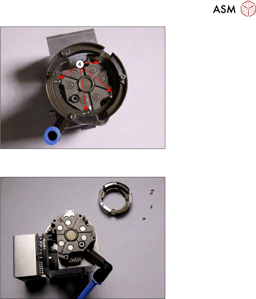
Fig.217:
► Remove the four screws (4) (Allen 1.27 or 1.5, depending on the screw type) holding the bay-
onet ring (2).
Fig.218:
► Lift the bayonet ring (2) up and off.