00195982-03_SM_SWS_EN.pdf - 第40页
2 Overview of the SIPLACE wafer system (SWS) 2.4 Description of SWS assemblies 40 Service Manual SIPLACE Wafer System (SWS) 11/2018 Fig.21: Main gripper assemblies (location 1/3) 1. Gripper 2. Toothed belt axis 3. Insta…
2 Overview of the SIPLACE wafer system (SWS)
2.4 Description of SWS assemblies
Service Manual SIPLACE Wafer System (SWS) 11/2018 39
Wafer changer
There are two different versions of the wafer changer. The version available depends on the loca-
tion (2/4 or 1/3).
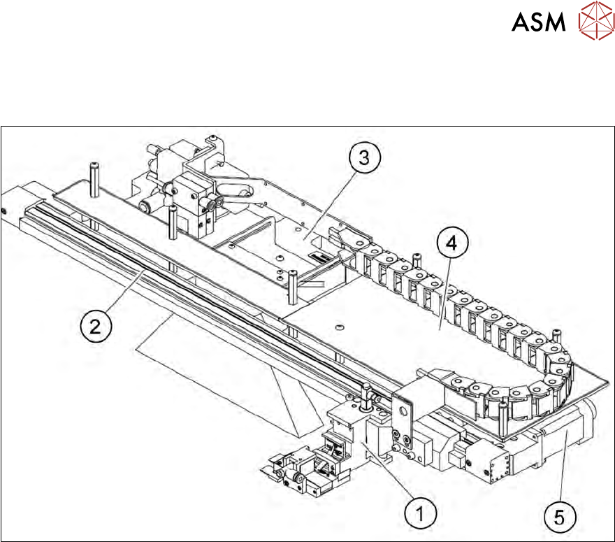
Fig.20: Main gripper assemblies (location 2/4)
1. Gripper
2. Toothed belt axis
3. Installation location for barcode scanner (optional)
4. AD-MOT board under the cover
5. Motor with coupling
2 Overview of the SIPLACE wafer system (SWS)
2.4 Description of SWS assemblies
40 Service Manual SIPLACE Wafer System (SWS) 11/2018
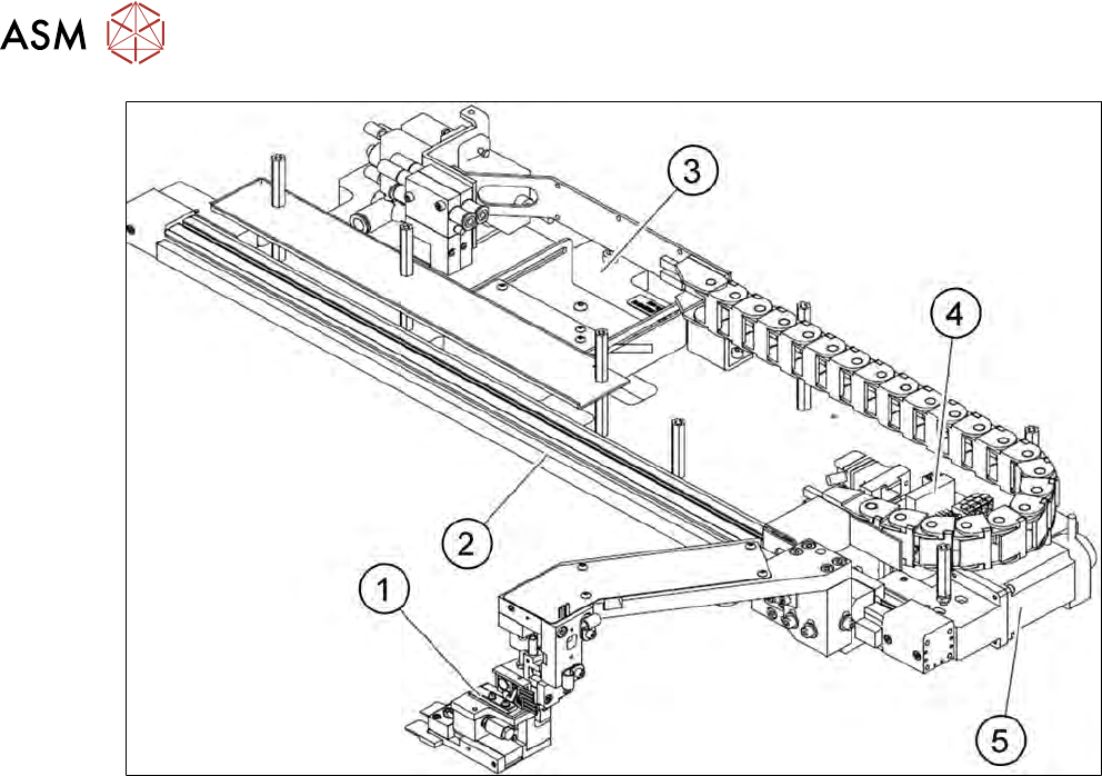
Fig.21: Main gripper assemblies (location 1/3)
1. Gripper
2. Toothed belt axis
3. Installation location for barcode scanner (optional)
4. AD-MOT board
5. Motor with coupling
2 Overview of the SIPLACE wafer system (SWS)
2.4 Description of SWS assemblies
Service Manual SIPLACE Wafer System (SWS) 11/2018 41
2.4.2 Optional features
2.4.2.1 Linear dipping unit (LDU)
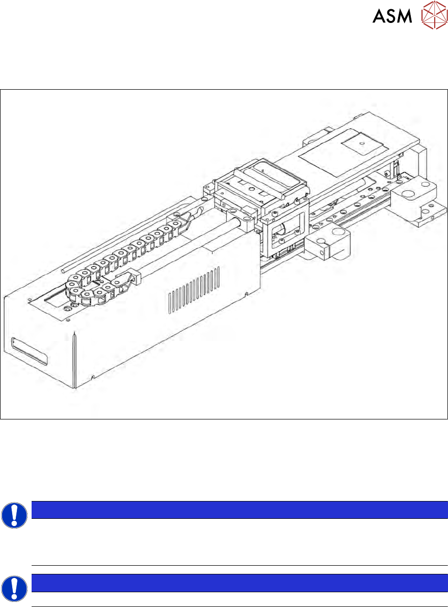
Fig.22: Linear dipping unit (LDU)
The LDU is needed to apply flux to the die during the flip chip process. This is necessary for ensur-
ing that the reflow process functions properly.
The LDU is able to apply highly accurate layers of flux. This flux is made available in a so-called
cavity. The depth of the cavity determines the thickness of the flux layer.
NOTICE
The LDU is, in principle, suitable for all types of flip chip flux.
► Only use epoxide and solder pastes after internal factory tests have been performed.
► If in doubt, contact the SIPLACE service team.
NOTICE
► Do not use the the LDU together with the die attach unit.