00195982-03_SM_SWS_EN.pdf - 第377页
15 Calibration 15.3 Calibration die handling - flip unit Service Manual SIPLACE Wafer System (SWS) 11/2018 377 Fig.542: ► After successful automatic calibration of the Z axis, the status changes to Ready . ► The calibra…
15 Calibration
15.3 Calibration die handling - flip unit
376 Service Manual SIPLACE Wafer System (SWS) 11/2018
15.3.2.3 Calibration – flip head Z axis
NO RISK OF SERIOUS INJURIES
► Setup mode not activated!
Machine covers are closed!
This calibration detects the correct zero point of the flip head Z axis with respect to the raceway of
the flip head rotation axis.
After the calibration, the actuator of the flip head Z axis is exactly positioned with respect to the
raceway, so that there is no effect on the Z axis during the rotation and there is finally no deviation
of the ball bearing!
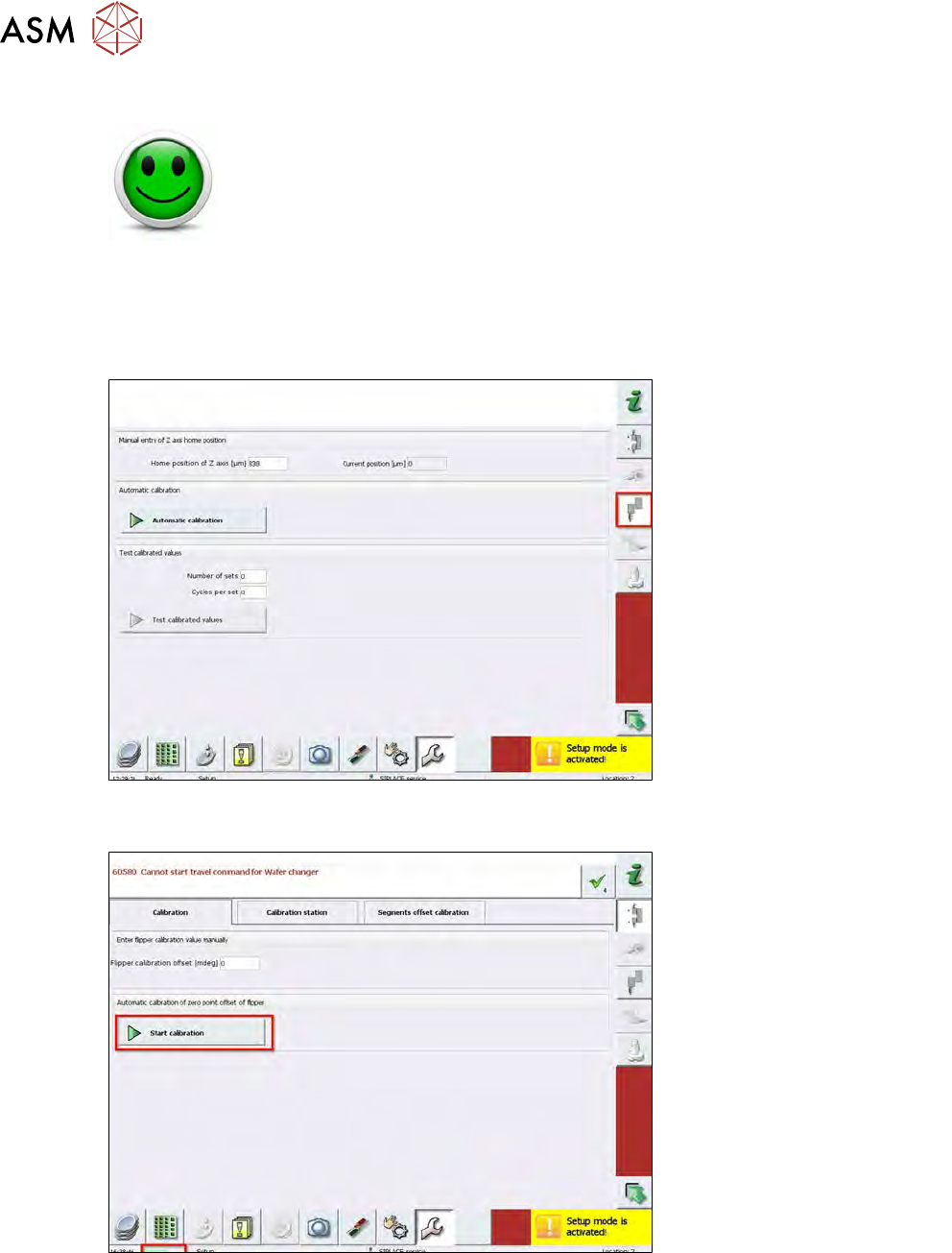
Fig.540:
► Choose Service Calibration Z axis on the right menu bar.
Fig.541:
► Choose Start Calibration.
ð The complete automatic calibration of the Z axis starts.
► During the automatic calibration, the status Execute is active.
15 Calibration
15.3 Calibration die handling - flip unit
Service Manual SIPLACE Wafer System (SWS) 11/2018 377
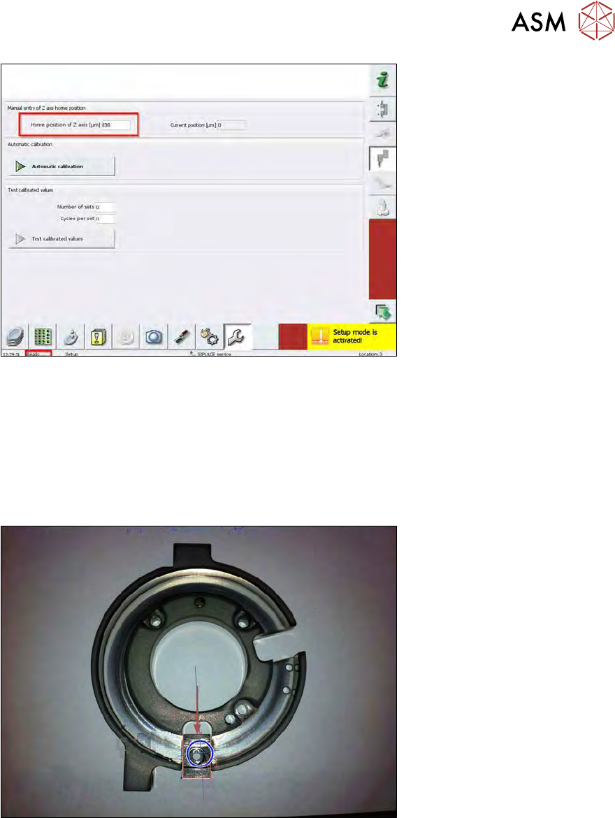
Fig.542:
► After successful automatic calibration of the Z axis, the status changes to Ready.
► The calibrated Z axis zero point correction value is shown at Home position of Z axis (µm).
How Automatic calibration for the flip head Z axis works
●
The Z axis holding cylinder is used as the start home position for the Z axis.
●
The flip rotation axis is moved to the home position.
●
The flip head rotation axis is rotated to the right by a defined value.
Fig.543:
●
The Z axis is moved down until the the time-out when the bearing touches a segment.
●
This Z value is saved.
15 Calibration
15.3 Calibration die handling - flip unit
378 Service Manual SIPLACE Wafer System (SWS) 11/2018
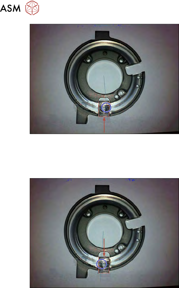
Fig.544:
●
The Z axis is moved up until the the time-out when the bearing touches a segment.
●
This value is saved.
●
From these two values, the home position for the Z axis is calculated (average value).
●
The flip head rotation axis is rotated to the left by a defined value.
Fig.545:
●
The Z axis is moved down until the the time-out when the bearing touches a segment.
●
This Z value is saved.