00195982-03_SM_SWS_EN.pdf - 第156页
7 Die ejector 7.5 Mechanical adjustment of the die ejector unit in the Z direction (focus) 156 Service Manual SIPLACE Wafer System (SWS) 11/2018 7.5.1.1 Preparatory tasks ► Move the wafer table to the change position. ► …
7 Die ejector
7.5 Mechanical adjustment of the die ejector unit in the Z direction (focus)
Service Manual SIPLACE Wafer System (SWS) 11/2018 155
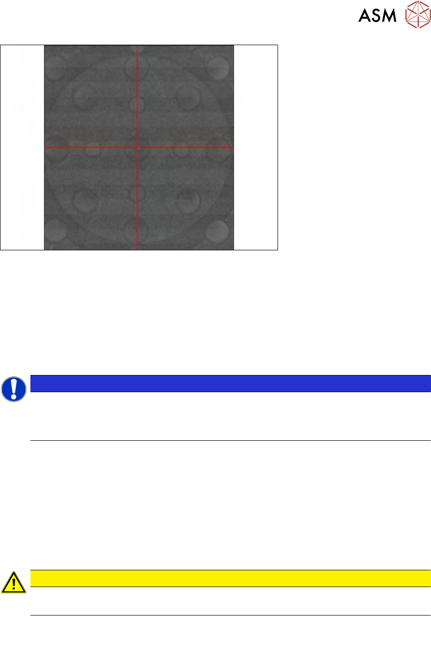
Fig.197:
► The needle tip (bright dot in the center) is now directly in the camera center (red crosshairs).
► Retighten the locking screws on the eccentric shaft (6) (Y direction).
► Check the camera live image to see whether the needle tip is still in the camera center.
► Adjust until this position remains and the eccentric shaft locking screws are tight.
► Now carefully tighten the four screws fastening the base plate (1 und 2). Keep an eye con-
tinuously on the wafer camera live image to check the relationship of the needle tip position to
the camera center.
NOTICE
If you notice a trend when tightening the fastening screws, which relates to the amount
which the needle center moves in the X direction, you can set this deviation in the opposite
direction with the eccentric shaft, so that the needle tip is once again in the camera center
after the four fastening screws have been fully tightened.
► You may need to adjust multiple times.
ð Once all four fastening screws (1, 2 and 6) have been tightened, the needle tip should be
exactly in the camera center point!
7.5 Mechanical adjustment of the die ejector unit in the Z
direction (focus)
7.5.1 Replacing the needle ejection system needles
CAUTION
Risk of injury from the sharp needles
There is a risk of injury from the sharp needles in the needle unit.
There are two different versions of the needle ejection system.
Old version: Needle ejection system with bayonet connection (no longer supplied)
Current version: Needle ejection system with magnetic fastening
In the event that a needle ejection system with bayonet fastening is damaged, it will be necessary
to upgrade to the new version with magnetic fastening (see 7.6 "Converting the bayonet needle
ejector unit (old version) to the magnetic needle ejector unit (current version)" [}168].
7 Die ejector
7.5 Mechanical adjustment of the die ejector unit in the Z direction (focus)
156 Service Manual SIPLACE Wafer System (SWS) 11/2018
7.5.1.1 Preparatory tasks
► Move the wafer table to the change position.
► Move the die ejector upwards.
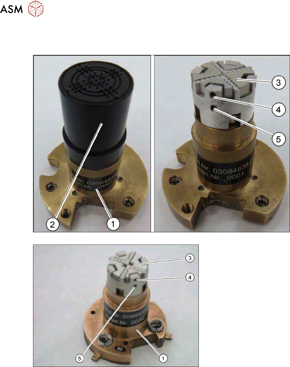
Fig.198: Needle unit for die ejector, magnetic
Fig.199: Needle unit for the die ejector with bayonet fastening (if still used)
► Twist the needle unit (1) off the lock.
► Pull the black cap (2) off. The needles (3) are located under the cap.
ð The needles are clamped in four sectors. One needle is in the center.
► The grub screws (4) at the four segments clamp the needles into place in the needle unit.
The center needle is held in placed by the bottom grub screw (5).
7 Die ejector
7.5 Mechanical adjustment of the die ejector unit in the Z direction (focus)
Service Manual SIPLACE Wafer System (SWS) 11/2018 157
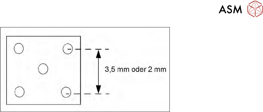
Fig.200: Diagram of the needle position (example)
●
Ejection system, 5 needles with 3.5 mm spacing [00385535-xx]
●
Ejection system, 5 needles with 2 mm spacing [00386908-xx]
► The 2x2mm needle kit requires a central needle fixture with a threaded pin 2x2mm, tightened
with a torque of 10Ncm.
► Depending on the application, fit the relevant needles into the openings in the four segments.